Post-processing
There are following tools available:
Common
Result Settings
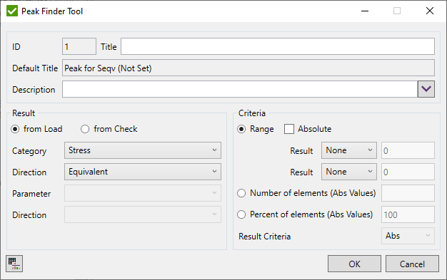
The peaks for Governing Load and Peak Finder tools can be found for Load or Check Results. Select from Load or from Check option in the Result group box.
For the Load Results choose the Category and the Direction:
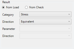
Note: Only element-based result categories can be selected (e.g. Stress, Element Force).
The parameter and the direction should be defined for the Check Result:
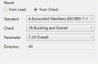
Note: All checks calculated for loads (except joint checks) can be selected.
Note: Governing load can be calculated only on the Load Group. Besides, only checks with Load Calculation = All Loads are displayed in the filter.
Filter Criteria
Filter Criteria allows to set limits that determine the results which are treated as peaks by the following options:
- Range - set upper/lower limit for the values to filter. For example, |Stress X| ≥ 160MPa:
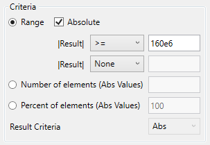
If an Absolute option is ON it means that the absolute value of the result is used for the criteria. Compression stress -160 Mpa will pass the above criteria.
- Number of elements - an amount of the elements with the Min/Max/Abs results (based on Result Criteria option).
- Percent of elements - % of all the model elements with the Min/Max/Abs results (based on Result Criteria option).
Peak Finder
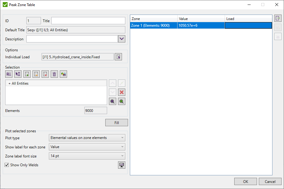
Peak Finder finds all peak zones based on the output results and presents them using a special plot and a summary table.
To add Peak Finder execute from the ribbon.
Select the type of result (Load or Check) using Result Settings
Set limits for peak values using Filter Criteria
To preview the results press  .
The following table will be shown:
Select Load using Load Selector. For the checks, it is possible to select only that type of the load that is supported by the check.
Define the Selection using Selector Control and press .
It is possible to preview the peak zones on the model. Select the zones in the table and press  .
.
Plot type - defines what values should be plotted on the model:
- Elemental values on zone elements - plot original values of the elements of the selected zones;
- Elemental values on zone elements + attached elements - plot original values of the elements of the selected zones and attached elements. For example when zones are very small (1 or 2 elements);
- Elemental values on selection - plot original values of all elements from the selection (ignoring elements from the zones).
Note: Labels will be displayed only for selected zones in the table. Show Only Welds option will be ignored.
- Absmax zone value on zone elements - plot all elements of the zone with the absmax value on the zone to keep each zone in a single color;
- Average on zone - plot all elements of the zone with the average value on the zone to keep each zone in a single color;
- Elemental values with zones average labels - plot original values of the elements of the selected zones and display label average value of each zone;
Show labels for each zone - put labels based on selected option near the element with a maximum value of the zone:
- None - do not show any labels;
- Id - id of the zone (e.g. "z1");
- Value - average or absmax value over the elements of the zone;
- Id and Value - zone id and zone average or absmax value (e.g. "z.1=123456");
Zone label font size - defines the label font size for all labels of the plot.
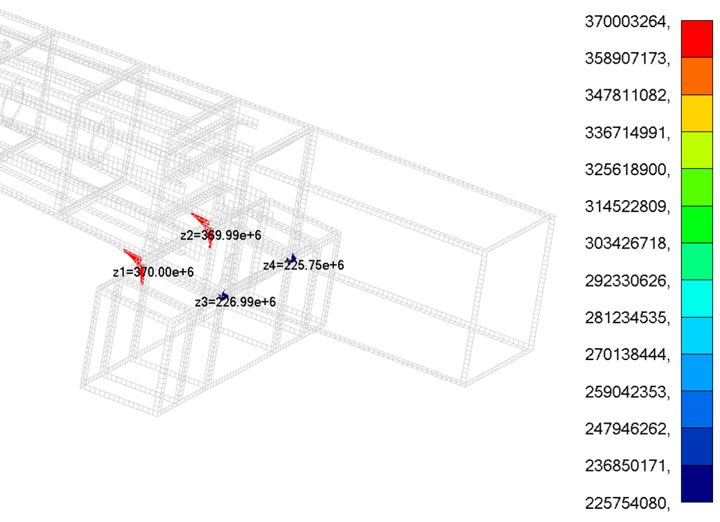
The Show Only Welds options are designed for a large model with a small mesh. The plot is shown only with the peaks and the welds elements. Show Only Welds = ON:
Show Only Welds = OFF:
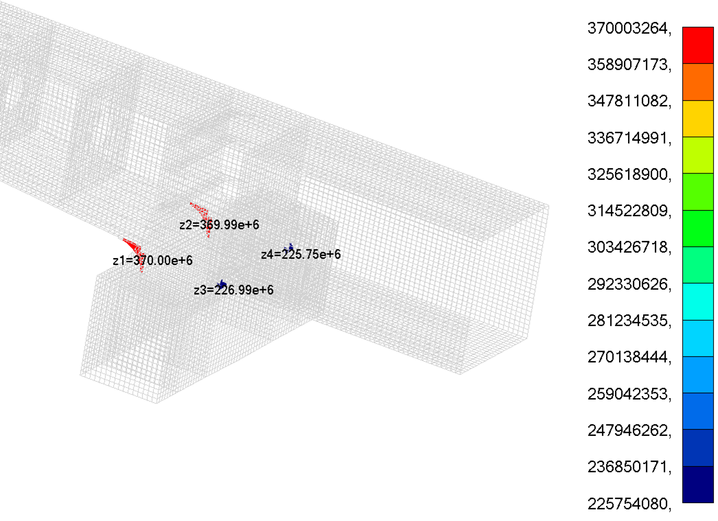
Note: Weld elements are taken from the Weld Finder Tool. If no welds are recognized the elements with free edges will be displayed.
Press  to export selected zones using Export Menu;
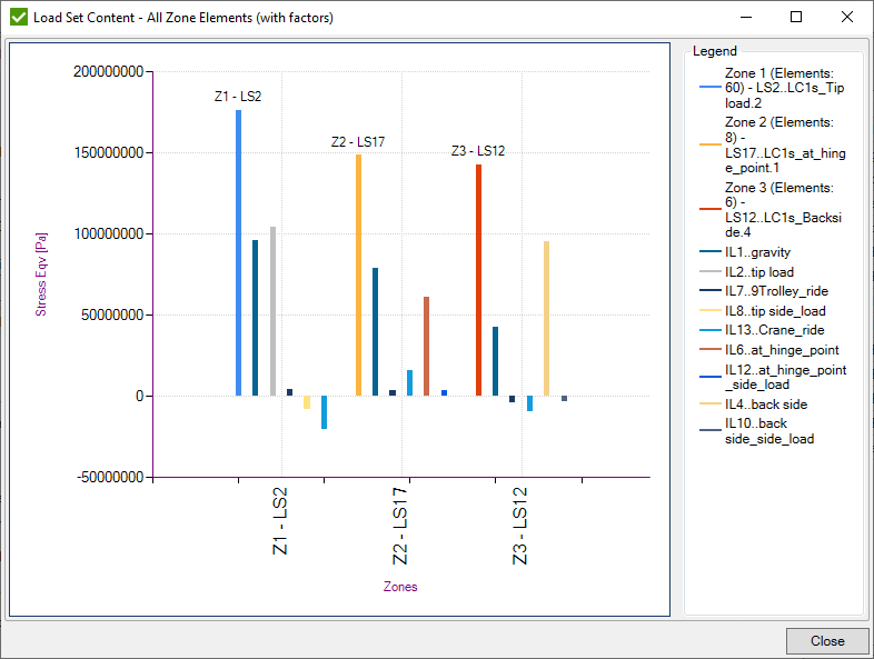
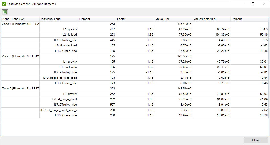
For all selected Zones where the type of the Load is Load Set it is possible to preview the portion of the Individual Loads in diagram or table:

- Load Set Content - Peak Element (with factors) - a diagram that displays the portion of result for all individual loads in load set multiplied on factors on the worst element of each selected zone;
- Load Set Content - All Zone Elements (with factors) - a diagram that displays the portion of result for all individual loads in load set multiplied on factors. The worst element for each Individual Load is calculated separately;
- Load Set Content - Peak Element - a table that displays the portion of result for all individual loads in load set multiplied on factors on the worst element of each selected zone;
- Load Set Content - All Zone Elements - a table that displays the portion of the result for all individual loads in load set multiplied on factors. The worst element for each Individual Load is calculated separately;
 - create a new
Governing Load Tool from all selected zones in the list. Each zone will be represented as a separate selection. Only results of Load Groups can be exported to Governing Load.
Governing Loads
Governing Loads - finds the critical (governing) loads from a large group of load combinations.
To add the Governing Loads tool execute from the ribbon.
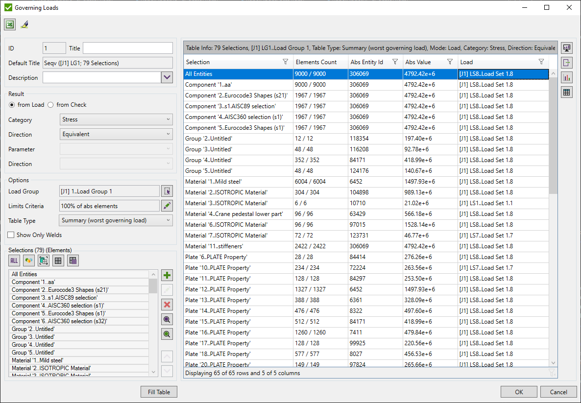
Select the type of result (Load or Check) using Result Settings
Set limits for peak values using Filter Criteria
Select Load Group using Load Selector.
Define Selections using Selection List Control and press .
Table Type - define the structure of the table (short or detailed):
- Summary (worst governing load) - display the worst governing load for each selection in the list;
- Expand (all governing loads) - display all governing loads for each selection in the list;
- Detailed (for each element) - display result for all governing load elements for each selection in the list;
Show Only Welds - plot is shown only with the peak values and the welds elements from Weld Finder Tool;
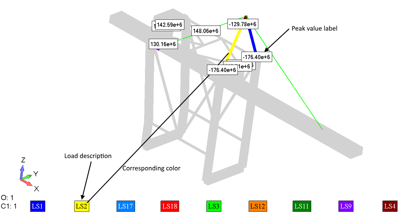
It is possible to plot elements of all/selected governing loads in the list in colors and put labels of load description:
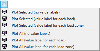
In addition, it is possible to include the following labels:
- For each load - put one label with Peak Value at the center of corresponding elements;
- For each load zone - when load generates peaks at different locations of the model, a label will be shown for each connected zone with max value on each zone.
Note: if governing load row is selected in the list - all elements related to governing load will be selected for a plot.
Note: if selection row is selected in the list - all elements related to selection will be selected for a plot.
Press  to export governing loads to a Load Group. It is possible to export selected or all governing loads in the list:

For all selected Governing Loads where the type of the Load is Load Set it is possible to preview the portion of the Individual Loads for the worst element in diagram or table:

 - open expand table for selected Load Group and
selected rows with selections in the table depending on Result Settings type (Load or Check);
Freebodies
Freebody - calculates a balanced set of forces/moments on a chosen part of a model. It is possible to retrieve internal/external loads to be used for substructure modeling or find contact/connector forces by manipulating with a custom selection of nodes/elements.
To add the Freebody tool execute from the ribbon.
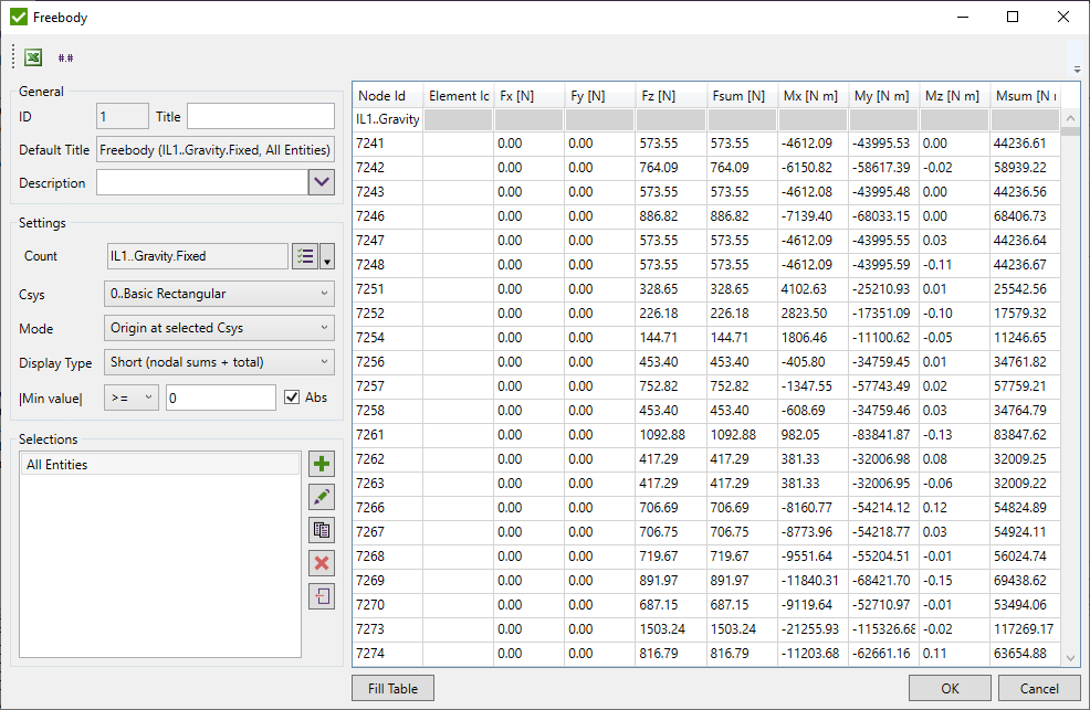
Loads - selected necessary loads using Multiple Load Selector. Each load is calculated separately per each selection.
Csys - coordinate system used to rotate forces/moments;
Mode - calculate the origin at selected nodes (for each created selection separately) or take the origin of selected Csys (same for all selections);
Display type:
- Short (nodal sums + total) - display the summarized result on each node from attached elements;
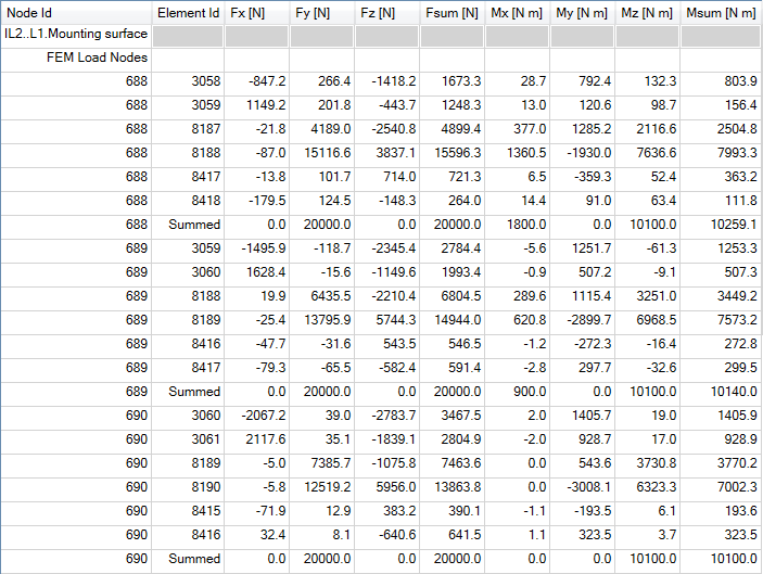
- Detailed (corner results + total) - detailed result on all nodes from selection and each attached element to respective node:
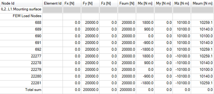
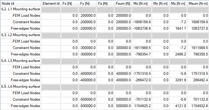
- Total (overall summation) - summarized values on all nodes of respective selection pair:
 - display only rows where all
forces/moments on each node satisfy set condition (e.g. skip small values).
Note: Condition is ignored for summation rows.
Selections - list of selection pairs (elements and nodes) to calculate freebody on. The result is calculated on each selection pair separately.
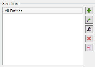
 - add new selection pair:
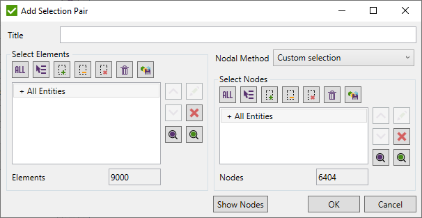
Title - selection pair title. If not set - sa hort description of elemental selection will be used by default.
Pick elements using Selector Control
Nodal Method:
- All nodes from elements - pick all nodes from selected elements automatically;
- Free-edge nodes from elements - find all nodes free-edges of selected elements. Useful with selections that include holes;
- Custom selection - manually pick necessary nodes using Selector Control.
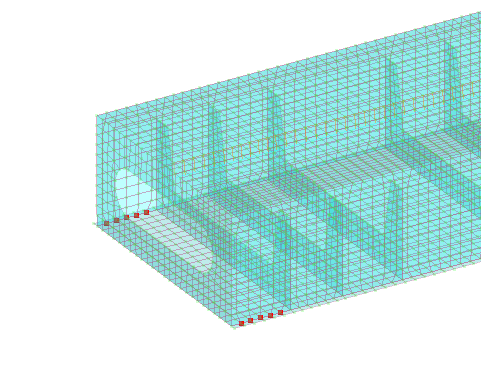
- displays nodes on a model that will be used in calculations:
 - edit selected selection pair;
 - copy selected selection pairs;
 - remove selected selection pairs;
 - import selections from components/groups;
Press to display results.

