DNV RP-C203 (2016)
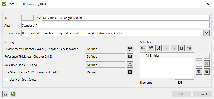
DNV RP-C203 Recommended practice for Fatigue Design of offshore steel structures (April 2016). Calculations cover environment air (chapter 2.4.4) and seawater with cathodic protection (chapter 2.4.5) based on stress calculation method B (chapter 4.3.4)
To add the standard execute from the ribbon:
Press  to Set Standard Custom Settings
By default Environment characteristic for full model is set to air environment. Press  to edit Environment type.
![]()
Thickness Factor is calculated based on formula:
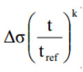
Tref - reference thickness equal to 25 mm for welded connections other than tubular joints. For tubular joints = 16 mm, for bolts = 25 mm.
K - thickness exponent on fatigue strength as given in Table 2-1, 2-2, 2-3 and 2-4.
By default, for non-welded elements the thickness factor is set to 1. For welds it is calculated with the reference thickness 25 mm. Press to edit Reference Thickness type:
![]()
SN Curve is directional classification. X - direction is parallel to the weld, Y - perpendicular. First set non-welded curve for full model. Second step is to define SN curve for welds (parallel and perpendicular). For welds intersection (last step) the lowest class between X, Y should be set.
![]()
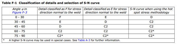
SN curve is recalculated based on principal stress angles and Table F-1 from F4. Comm. 2.3.2:
![]()
For C2* (-1) is used user defined SN curve.
Note: SN curve defined for parallel direction (X) is taken as max class to use. E.g. if user set D curve for X and F curve for Y:
0-30 F
30-45 E
45-60 D
60-75 D
75-90 D
Stresses are calculated based on method B from chapter 4.3.4:
Method B
For modelling with shell elements without any weld included in the model the hot spot stress is taken as the stress at the read out point 0.5t away from the intersection line.
For modelling with three-dimensional elements with the weld included in the model the hot spot stress is taken as the stress at the read out point 0.5t away from the weld toe.
The effective hot spot stress range is derived as:
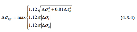
When the nominal stress S-N curves are used, the stresses extracted from the finite element model may use Method B without inclusion of the 1.12 factors in equation (4.3.4). By default factor is used for full model, can be changed in characteristic.
