Weld Finder
Weld finder is a tool that performs search of welds on a model. Weld consists of weld parts. Each weld part is a set of elements from one side of welded connection. Weld part can be welded or non-welded and has its own properties: weld length, weld type, throat thickness etc.
Note: Having the welds recognized is enough to perform fatigue calculations where elemental stresses will be automatically rotated into a weld direction.
Note: Weld dimensions are required for defining stresses in weld based on force and area which are used in weld strength calculations. Weld dimensions are not necessary to be set if only fatigue calculations should be performed.
To add Weld Finder execute from the ribbon.
Welds Recognition:
 - open Free Edge Finder tool to perform search on free edges that can influence on the recognition process.
Press  to automatically highlight single selected weld/weld part from the list.
Settings:
Selection - set custom selection if it is necessary to perform the search only on a part of the model.
Each Weld Title = Default Weld Title + ID + [weld origin coordinate].
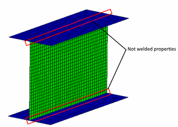
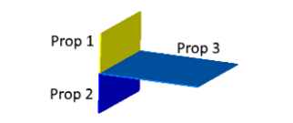
Not welded properties - a connection places between the properties where a weld will be ignored during the recognition. For example, beam is modeled with plates:
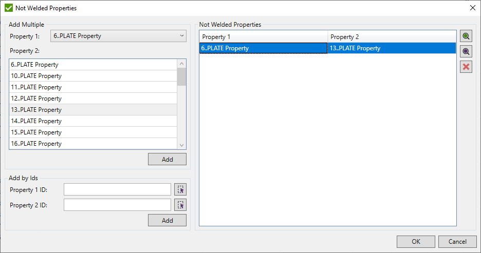
Add multiple:
Select Property 1 from the drop-down list and the required items for the Property 2 and press . All combinations of Property 1 and Property 2 will be created.
Add by IDs:
 - pick property ID by the selected element from the model.
Press to add the property to the list.
Note: The existing combinations will be skipped. Combinations of the same property ids will be taken into account during the recognition.
 - preview only selected combinations;
 - highlight selected combinations;
 - remove selected combinations;
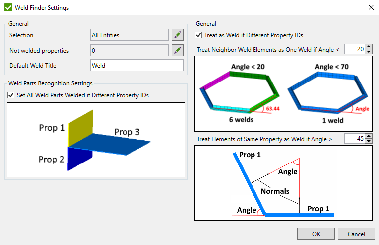
Treat as weld if different property IDs - in case two properties are of equal thicknesses the weld will be created if the option is ON.
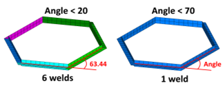
Treat neighbor weld elements as one weld if Angle < value - the angle that determines the straightness of the weld. In the example real angle = 63.44 and a set value of 20 degrees will provide 6 welds. If the set value is equal to 70 degrees - 1 weld is recognized.
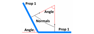
Treat elements of the same property as weld if angle A > set value - if two elements of the same property form the angle that is more than the defined, these two elements will form a weld.
Set all weld parts welded if different property IDs - if all weld parts of a weld connection are formed by different properties they will be automatically set as welded.
Press  to perform welds recognition.
If weld finder already contains welds - the following window will appear:
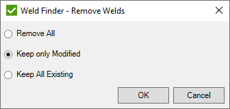
- Remove All - remove all existing welds before recognition.
- Keep only Modified - keep all welds where any parameter was modified (e.g. throat thickness, welded/non-welded part, etc.). The elements from these welds will be skipped during the recognition;
- Keep All Existing - keep all previously recognized welds. Elements from this welds will be skipped during the recognition.
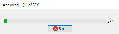
During the search, progress with a count of checked elements will be displayed:
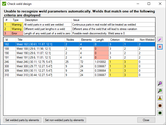
After the recognition is finished, all welds are checked on the design. If all weld parts of single weld are welded or all weld parts are not-welded, they will be included to the list of welds that are recommended to be checked manually:
Note: This method is equal if to press button in the weld finder window.
Note: If a weld consists of only 2 parts (e.g. Angle-weld), all parts will be set as welded but weld will not be included to the list.
 - edit selected weld;
 - remove selected welds;
 - highlight selected welds (highlight weld elements on entire model);
 - preview selected welds (only selected elements will be displayed);
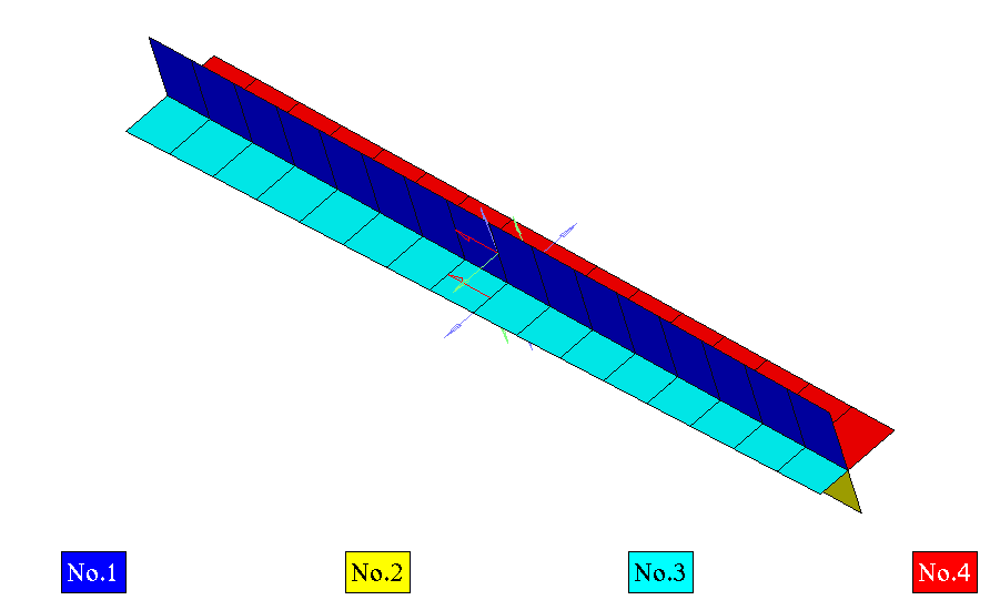
 - plot welded/non-welded parts of selected welds in colors;
 - plot selected weld Ids.
 - plot welded/non-welded parts of selected welds. Pick elements from necessary weld parts to set full weld part welded.
 - plot welded/non-welded parts of selected welds. Pick elements from necessary weld parts to set full weld part welded.
 - plot welded/non-welded parts of selected welds. Pick elements from necessary weld parts to set full weld part non-welded.
Note: Only one element from the respective weld part can be selected.
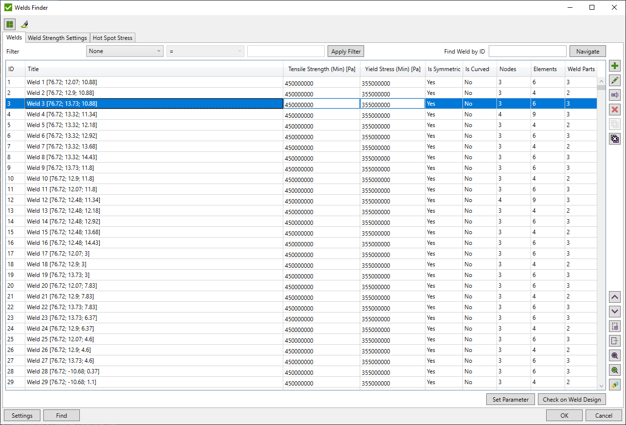
After weld design is checked, a full list of recognized welds is displayed:
Filter welds by Tensile (Min) or Yield (Min) properties of the weld.
Use Find weld by ID to select weld with already known ID.
 - edit selected weld;
 - rename selected weld;
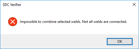
 - combine selected welds into one and add to the end of the list.
Note: Welds should be connected. An error message will be displayed otherwise:
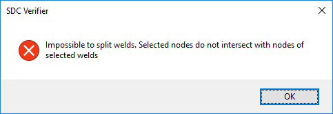
 - split selected welds at selected nodes and add new welds to the end of the list.
Note: At least one selected node should belong to selected welds. The error message will be displayed otherwise:
- remove selected welds.
Use  and
and  to change the welds order.
 - select element from the model and highlight welds in the list that contain selected element;
 - export selected welds in the list using Export Selected Items Menu:
- highlight selected welds (highlight weld elements on entire model);
- preview selected welds (only selected elements will be displayed);
The following plotting commands are available:
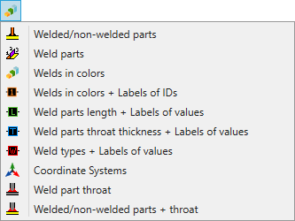
- plot welded/non-welded parts of selected welds in colors;
 - plot weld part numbers of selected welds in different colors;
 - plot weld colors only;
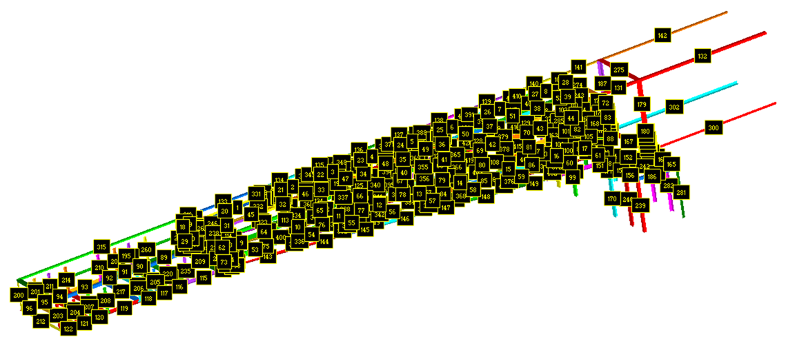
 - plot weld colors and the labels with Ids:
Example of plot with labels of Ids
- plot weld colors and the labels with lengths of weld parts;
- plot weld colors and the labels with lengths of weld parts;
 - plot weld colors and the labels with throat thicknesses of weld parts;
 - plot weld colors and the labels with the type of welds;
 - plot weld part numbers and coordinate systems of each weld part of selected welds:
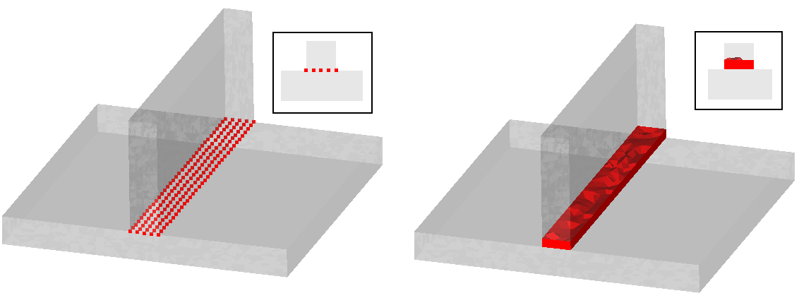
 - draw weld throat on the model:
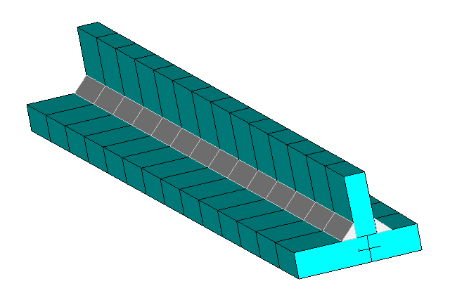
Note: Model thickness is taken into account for weld throat position;
 - plot welded/non welded parts and draw weld throat on the model;
Press  to open window and modify Tensile and Yield of the selected welds:
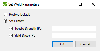
Restore Default - calculate minimum Tensile and Yield parameters on a full weld;
Set Custom - input custom values to be used in calculations. It is possible to set parameters separately.
Note: Tensile (Min) and Yield (Min) are calculated from all elements of the weld and are used in the weld strength calculations (optionally).
 - open window with a list of welds that are recommended to be checked manually.
Add Weld(s)
 - open menu to add weld by options:
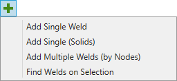
Add Single Weld - add beam/shell weld manually using Edit Weld Window
Add Single Weld (Solids) - add solid weld manually using Edit Weld Window (Solids)
Add Multiple Welds (by nodes) - recognize welds by selecting multiple weld node lines on the model. Nodes will be split on groups that are connected by mesh and all elements connected to the group will be recognized as a separate weld.
Note: Weld lines should not share common elements to create separate welds.
Find Welds on Selection - select model elements using Selector control and perform welds recognition on them.
Note: Selection defined in Settings is ignored. Rest of the options are taken into account.
Add/Edit Single Weld
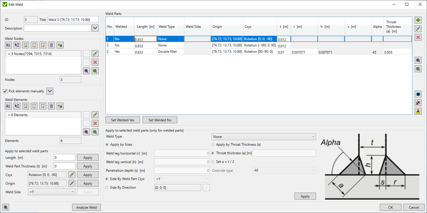
Weld Nodes - nodes that define welding line. Select nodes using Entity Rule Selector;
Weld Elements - elements that are connected to the weld nodes. By default, they are recognized automatically but sometimes element does not fit the required recognition settings (e.g. element is under a bigger angle that defined in settings). In this case, it is possible to modify elements manually. Enabled when the pick elements manually option is turned ON;
Pick elements manually - weld elements are defined by a user. Automatic recognition of elements is not performed;
Note: All weld nodes should belong to weld elements.
Note: The option is automatically disabled when the weld is in Add mode and enabled when in Edit mode.
- recognize weld elements from nodes. Enabled when the Pick elements manually option is turned ON;
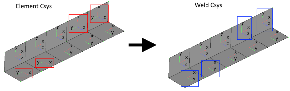
- perform recognition of weld parts and their properties (welded/non-welded, length, origin and coordinate system).
Note: A part is welded if:
- It does not form a plane with any other part and any other parts form a single plane (e.g. T-weld);
- It is the thinnest part of the weld. If all thicknesses are equal, all weld parts are non-welded;
- highlights weld elements on the entire model;
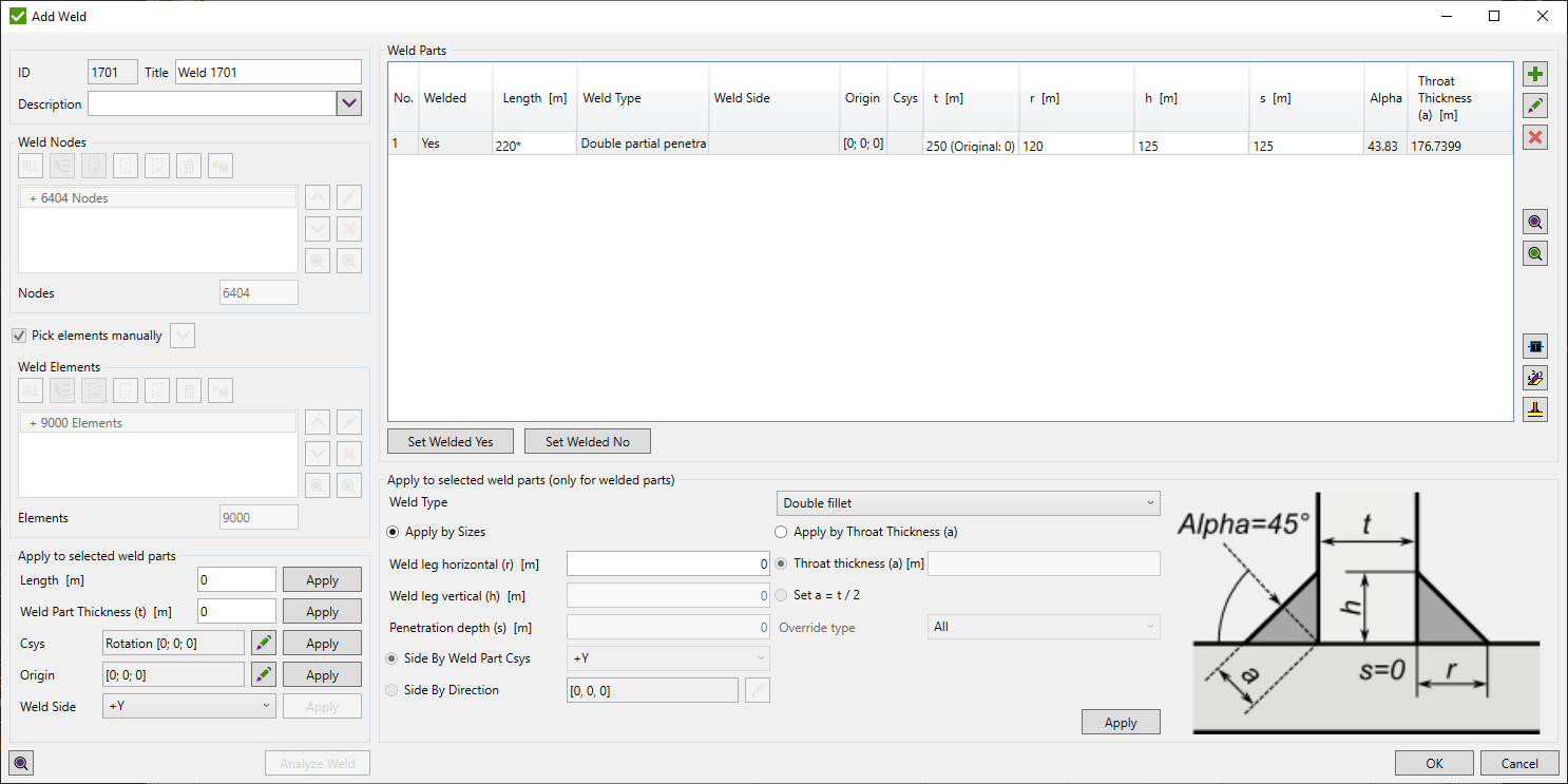
Apply to selected weld parts - modifies weld length, throat thickness, coordinate system and origin of selected weld parts.
Coordinate System can be defined by the rotational angles around global X, Y, and Z axes or by defining coordinate system vectors manually:
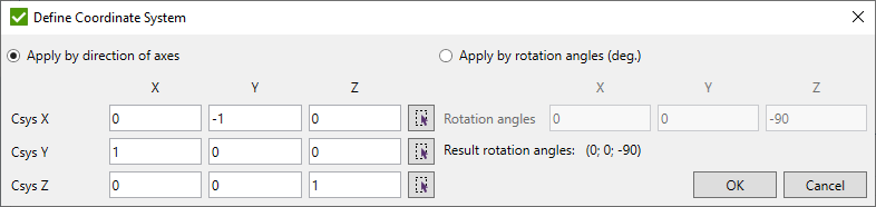
Result rotation angles - angles that will define the coordinate system;
If directions of axes are not perpendicular between each other, result rotation angles will display following message:

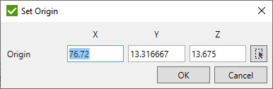
Origin can be set manually or picked from the model:
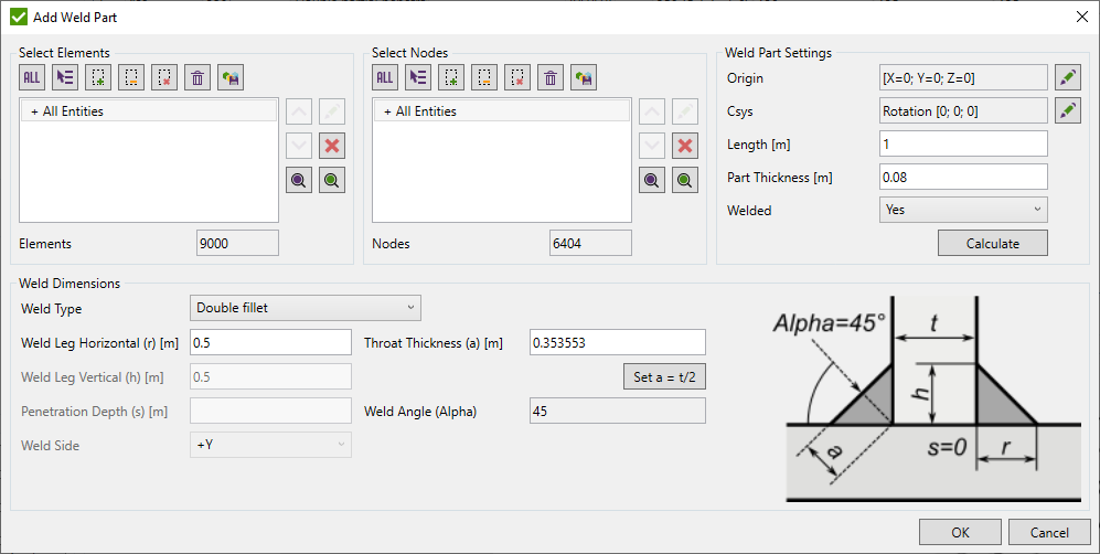
Apply for selected weld parts (only for welded parts) - apply a weld type and dimensions to welded parts.
Weld type - define the type of welding for a single weld part. None type is set by default.
Dimensions of the weld part define welding size. For different weld types dimensions can be set in a different way:
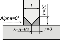
Double full penetration - all dimensions are calculated using weld part thickness as shown in the picture below:
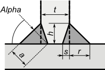
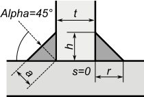
Double partial penetration - weld leg horizontal (r), weld leg vertical (h) and penetration depth (s) are input parameters. Alpha and throat thickness (a) are calculated automatically:
Double fillet - alpha is automatically set to 45°. If weld leg horizontal (r) = weld leg vertical (h) are inputs - throat thickness (a) is calculated automatically and vice versa.
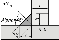
Single fillet - alpha is automatically set to 45°. If weld leg horizontal (r) = weld leg vertical (h) are inputs - throat thickness (a) is calculated automatically and vice versa. Weld side - it is possible to put +Y and -Y. +Y defines that weld part is along Y vector of Coordinate system of weld part; -Y - vice versa.
If apply by throat thickness is selected, it is possible to set custom throat thickness (a) or use a half of weld part thickness (t).
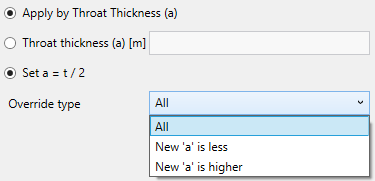
Override type - apply new thickness by options:
- All - set to all selected parts;
- New 'a' is less - apply only to parts where the new thickness is less than in existing part;
- New 'a' is higher - apply only to parts where the new thickness is higher than in existing part.
Add/Edit Single Weld (Solids)
Solid weld consist of solid weld parts that should be defined manually. For the weld strength calculations it is enough to define only weld parts that are welded.
All the settings are similar as described in Add/Edit Single Weld except Weld Nodes and Weld Elements are not possible to be selected as well as Analyze Weld button is disabled. Weld elements and nodes are automatically updated when weld part is added/edited/removed;
- Add new weld part:
Solid weld part nodes and elements should be selected on the surface of the welding to obtain correct force/moment summation for the Weld Strength calculation:
Press button to calculated Weld Part Settings automatically. Also it is possible to set all the settings manually.
Define Weld Dimensions if weld part is welded to calculate weld area/inertia for the weld strength calculations.
- Edit selected weld part;
- Remove selected weld part;
- Preview only elements of selected weld parts in the list;
- Highlight elements of selected weld parts in the list;
Weld Strength Settings
Weld dimensions are necessary to be set in case weld strength calculations should be performed.
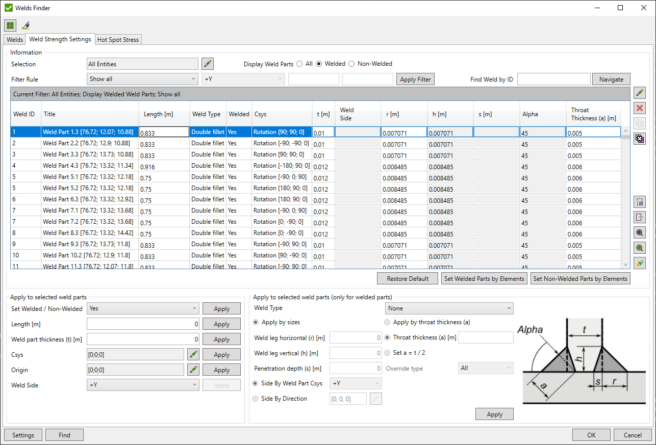
It is possible to filter welds by criteria:
Selection - select the part of the model where a filter will be applied.
Display Weld parts:
All - display both welded and non-welded parts;
Welded only - display only welded parts in the list;
Non-welded only - display only non-welded parts in the list;
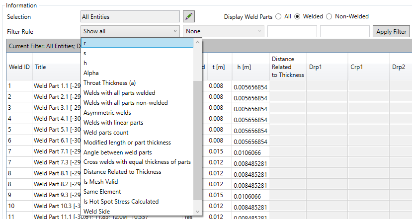
Filter Rule:
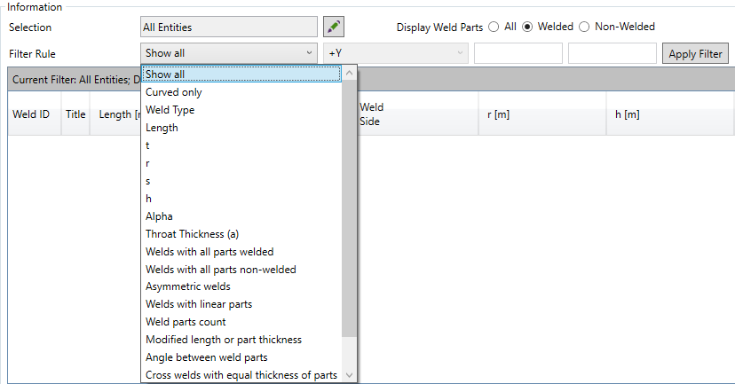
Show all - shows all weld parts on filter selection;
Curved only - shows only curved weld parts. Weld part is curved if any angle of the weld part exceeds 3°;
Weld Type - shows weld parts of selected type;
Length, t, r, s, h, Alpha, a - shows weld parts dimension matches the criteria (<, >, between the set values etc.);
Welds with all parts welded/non-welded - display only weld parts of welds that contain all parts welded or non-welded;
Asymmetric welds - display only weld parts of welds that are not perpendicular to each other (5-degree tolerance);
Welds with linear parts - display only weld parts of welds that contain beam/bar elements;
Weld parts count - display only weld parts of welds where amount of weld parts of the weld matches the criteria. 2 parts = corner or butt weld; 3 parts = T-weld; 4 parts = Cross weld;
Modified length or part thickness - display only weld parts where the length or part thickness was modified manually;
Angle between weld parts - display only weld parts where maximum angle between all weld parts matches criteria. For example, butt welds can be found be setting the value approx. 0;
Cross welds with equal thickness of parts - display only welds that contain 4 weld parts with equal thickness (t);
Weld Side - show single fillet weld parts of the selected side;
Press to display weld parts by selected criteria;
Apply to selected weld parts - apply weld length, throat thickness, coordinate system and origin to all selected weld parts. It is possible to Set Welded/Non-Welded or set an opposite value (Invert) to the current option of the weld part;
Apply dimensions to selected weld parts - apply dimensions to weld parts of the selected type. A detailed explanation can be found in Add/Edit Weld.
Note: Edit, combine, split, remove, preview and plot commands work for selected welds despite weld parts are shown in the table. All commands are described in Welds Recognition chapter.
 - restore original length, weld part thickness and weld sizes of all selected weld parts. Weld type, in this case, will be set to None.
open window to export selected weld parts and related welds:
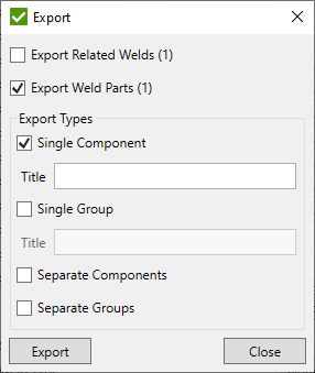
By default, selected weld parts and single component options are selected.
Export welds (count) - all welds that contain selected weld parts;
Export weld parts (count) - all selected weld parts;
Single component - create one component from the elements of selected welds or weld parts. Set the Title of the component if the option is ON. A default title with the amount of selected welds/weld parts will be used otherwise;
Single group - create one group from the elements of selected welds or weld parts. Set Title of a group if the option is ON. A default title with the amount of selected welds/weld parts will be used otherwise;
Separate components - create a separate component from the elements of each selected weld or weld part;
Separate group - create a separate group from the elements of each selected weld or weld part.
Note: Export types are applied separately to welds or weld parts options.
Hot Spot Stress
Hot spot locations should be set to interpolate stresses from the reference points in order to calculate Hot Spot Stresses that can be used in fatigue calculations.
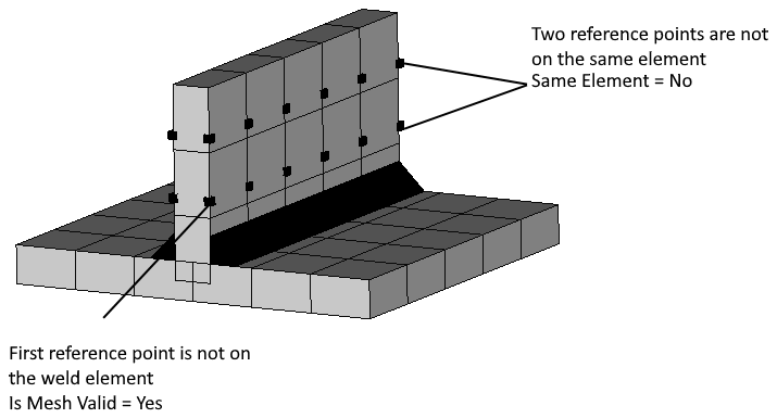
In order to obtain correct stress interpolation, reference points should not be located at the same element and first interpolation point should not be located on the element of the weld part:
It is possible to filter weld parts by criteria. Most of the filter options are described in Weld Strength Settings.
Filter Rule:
The following options are available only for Hot Spot Stress:
Distance Related to Thickness - display weld parts that are calculated by coefficient * t or the value in model units;
Is Mesh Valid - display weld parts with the first point location (Yes - located farther than the weld part elements; No - located on the weld part elements);
Same Element - display weld parts with the reference points locations (Yes - points are located on the same element; No - points are located on different elements);
Is Hot Spot Stress Calculated - display weld parts with or without defined hot spot stress locations;
Press to display weld parts by selected criteria.
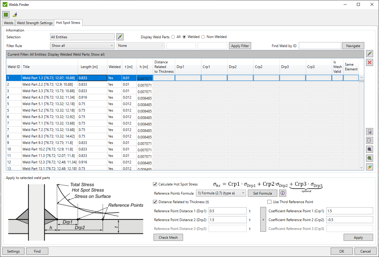
Hot Spot Location Settings
Hot Spot Location Settings are applied to all selected parts. It is possible to use predefined settings or fill in the custom distances and coefficients:
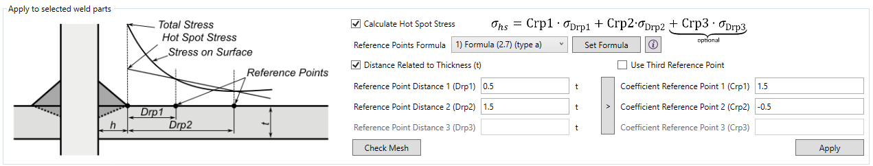
Calculate Hot Spot Stress - enable/disable Hot Spot Stress calculations for selected weld parts. By default Hot Spot Stresses are not calculated for all weld parts.
Hot Spot Stresses are calculated for each welded node and respective point of interest (top or bottom) of the element by the following interpolation formula:
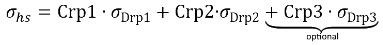
Where
Crp1, Crp2, Crp3 are interpolation coefficients;
σDrp1, σDrp2, σDrp3 - nominal stresses at the reference points at distances Drp1, Drp2 and Drp3;
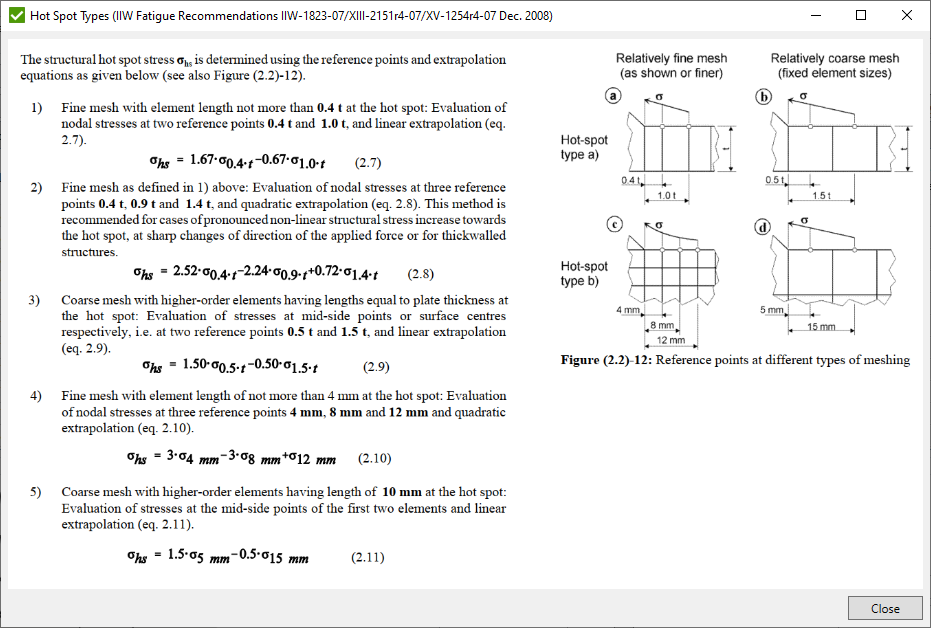
Select Reference Points Formula and press Set Formula to apply coefficients. By default reference point settings are based on IIW Fatigue Recommendations IIW-1823-07/XIII-2151r4-07/XV-1254r4-07 Dec. 2008:
Distance Related to Thickness - take distances as coefficient * t if turned on or by custom distance in model units otherwise;
Use Third Reference Point - enable/disable usage of third reference point to have a quadratic interpolation by 3 points;
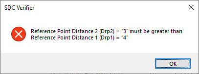
Reference Point Distance 1, 2, 3 - distances from the weld toe that are based on weld part vertical leg size (h). Input value depends on the Distance Related to Thickness (t) option. If option is turned ON - distance is calculated as an input value * weld part thickness (t). Otherwise custom distance in model units should be filled in.
Note: Drp1 < Drp2 < Drp3. Error message will appear if conditions are not met:
Note: Weld part vertical leg size can be set in the Weld Strength Settings. If size is not set - Hot Spot Stress will be calculated at the intersection of weld parts instead of the weld toe.
Coefficient Reference Point 1, 2, 3 - interpolation coefficients that are based on reference point distances.
In case custom reference point distances are used - it is possible to calculate coefficients automatically by pressing
 button.
Press Check Mesh button to refresh mesh validity states for selected weld parts.
Press Apply to apply Hot Spot Location Settings to the selected parts. Mesh validity checks will be performed automatically.
Hot Spot Location Plot
 - plot settings of selected weld parts.
- plot welded/non-welded parts of selected welds in colors;
- plot weld part numbers of selected welds in different colors;
- plot welds of selected weld parts in colors only;
- plot welds of selected weld parts in colors and put the labels with Ids;
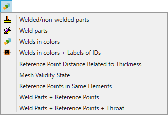
Reference Point Distance Related to Thickness - display label plot of selected weld parts if distances is based on weld part thickness (t) or on custom distance;
Mesh Validity State - display label plot of selected weld parts if first reference point is located on the weld part element;
Reference Points in Same Elements - display label plot of selected weld parts if reference points are located on the same element;
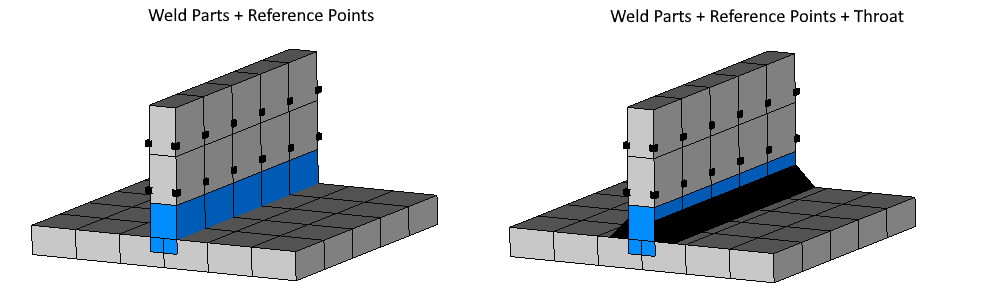
Weld Parts + Reference Points - display selected weld parts in colors and draw locations of reference points in the model;
Weld Parts + Reference Points + Throat - display selected weld parts in colors and draw locations of reference points and weld part throat in the model;
Weld Stresses
Fatigue
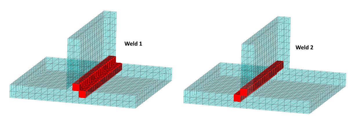
To perform a fatigue checks on welds it is enough to recognize welds without setting the weld sizes. The elemental stresses are used and stresses for each weld element should be oriented into the weld direction. This is performed automatically without reorientation of elements in the model. So no rerun of the analysis is needed:
X - parallel the weld.
Y - perpendicular to the weld.
If element belongs to multiple welds (e.g. intersections) - weld stresses for fatigue calculations will be oriented using the direction of the last weld in the list of the Weld Finder Tool.
Weld Stresses are, therefore, implemented as a separate category of result. All the tables/plots for stresses also can be created for the weld stresses.
Fatigue calculation solid welds are detected automatically and performed on the free face.
Note: The Equivalent direction is calculated using converted X, Y and XY directions.
Note: Weld X direction for elements that are connected to the weld only at 1 node will be calculated using the connected node and a default neighbor weld node.
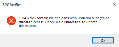
Note: If welds were not recognized, the original stresses will be used and the warning message will be shown:
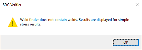
Note: For the elements that do not belong to any weld, the original stress will be used.
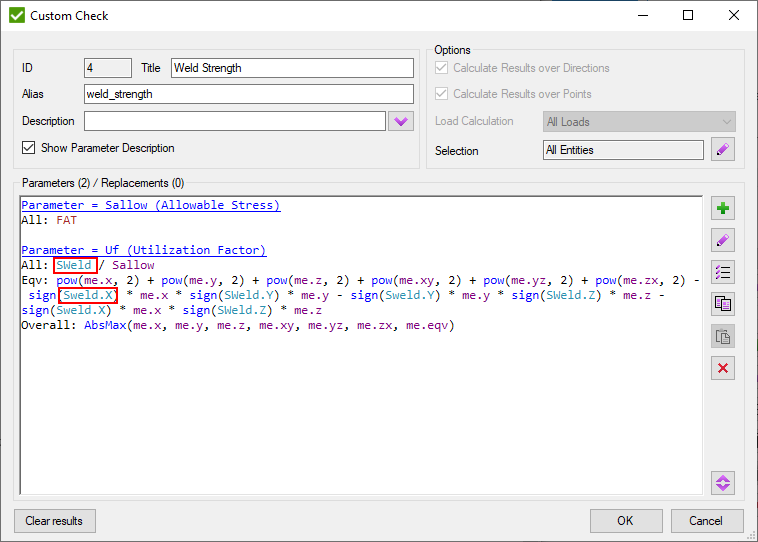
It is possible to use the weld stresses for the checks by using the Sweld variable in the formula editor. For example, the different allowable stresses for shear stress and normal stresses parallel and perpendicular to the weld orientation can then easily be accounted for:
Weld Strength
Weld stresses for Weld Strength checks are calculated using the elemental-nodal forces/moments (GP Forces/Moments) only from the weld nodes line and connected weld part elements as described in Weld Force Summation.
The forces/moments are rotated using the coordinate systems of the weld and Weld Stresses are calculated using the dimensions of the weld (Weld Leg sizes, weld throat etc.) to obtain the weld area and inertia.
Note: If weld dimensions are not set - the standard will not be created and the message will be shown:
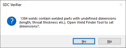
Note: If the welds were modified and the weld dimensions were not set after the standard had been created - the error message will appear during the calculation:
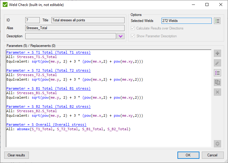
There is no separate result category for the weld stresses that are based on the forces/moments. To display the results it is necessary to create the respective standard and build the table or display the plot for the 'Total Stress' check. For example for check '7..Total stresses all points' in Eurocode3 Welds (EN1993-1-8, 2005) standard: