

How Friede & Goldman Verified the WindSetter WTIV Crane Pedestal with SDC for Ansys
318,311
finite elements in the structural model
0°–355°
crane boom range evaluated in 5° increments
20-year
fatigue design target met for the main pedestal scantlings
- Crane load cases organized. Operational slewing loads were converted into load combinations.
- DNV checks from ANSYS results. Yielding, buckling, fatigue, and reporting were processed from one large FE model.
- Designed for the planned operating life. The main pedestal scantlings met the 20-year fatigue design target for the planned crane operating profile.
Friede & Goldman needed to answer a specific design question: could the WindSetter WTIV main crane pedestal and the hull structure supporting it safely carry the reactions from the leg-encircling crane throughout its operating range while meeting the applicable DNV strength, buckling, and fatigue requirements?
This was not a check of the pedestal in isolation. As the crane slews, the direction and combination of vertical loads, lateral forces, overturning moments, and torsion change. Those reactions must be transferred from the pedestal into the surrounding deck, bulkheads, girders, and stiffeners.
The team solved the structural model in ANSYS Workbench and used SDC for Ansys to generate the required load combinations and perform DNV-based yielding, buckling, and preliminary fatigue checks from the same FE model.
Working with large models and offshore code checks?
SDC for Ansys helps engineering teams turn FEA results into structured verification workflows for yielding, buckling, fatigue, load combinations, and reporting. Use it to keep complex checks traceable across large models, many load cases, and standards-based requirements.
Explore SDC for Ansys
Project at a glance
- Company: Friede & Goldman, Ltd.
- Structure: Main crane pedestal and supporting hull structure
- Vessel: WindSetter WTIV
- Analysis workflow: ANSYS Workbench + SDC for Ansys
- Model size: 318,311 finite elements
- Standards basis: DNV offshore rules, including DNV-OS-C101, DNV-OS-C104, DNV-RP-C201, and DNV-RP-C203
- Checks performed: plate yielding, plate buckling, stiffener buckling, fatigue, load combinations, and reporting
- Outcome: sufficient pedestal strength confirmed; preliminary fatigue life exceeds the 20-year minimum requirement for the main scantlings
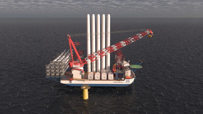
FO-146 WindSetter Class concept visualization, included to show the wider WTIV context of the crane pedestal analysis. Visualization courtesy of Friede & Goldman.
The engineering challenge
The crane pedestal is not an isolated component. It transfers large crane reactions into the surrounding WTIV structure, so the analysis had to cover both the pedestal itself and the supporting hull structure below it.
Three issues made the verification work demanding.
First, the finite element model was large. It represented the starboard aft section of the WTIV, extending aft from Frame 22, from centerline to starboard, and from baseline to the top of the pedestal. The primary structure was modeled with shell elements, while stiffeners such as bulb flats, small T-sections, and flat bars were modeled with beam elements. The model included decks, bulkheads, floors, transverse webs, stringers, girders, the crane pedestal, and relevant cutouts.
Second, the loading scope was broad. Because of the pedestal geometry and crane slewing range, the crane had to be evaluated across boom angles from 0° to 355° in 5° increments. Two crane cases were considered, covering lateral forces that create positive and negative torsional moments around the vertical axis.
Third, the amount of result data was significant. The team had to process strength checks, buckling checks, fatigue calculations, and report outputs across a large model with many load combinations. Managing this manually would have been slow and more exposed to review errors.
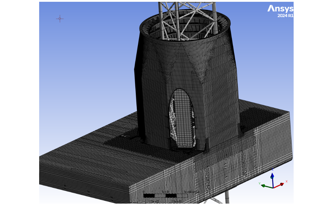
FEM mesh overview of the crane pedestal and supporting structure
How SDC Verifier was used
Friede & Goldman solved the structural model in ANSYS Workbench and used SDC for Ansys to process the verification workflow.
SDC for Ansys supported the project in five main areas:
- generation of load combinations;
- plate yielding checks;
- plate and stiffener buckling calculations;
- fatigue evaluation;
- reporting.
For yielding checks, SDC for Ansys compared element stresses against allowable stress limits and calculated utilization factors for each stress type. The workflow allowed the team to review maximum utilization across normal stresses, shear stresses, and von Mises stress in one result view.
For buckling, SDC for Ansys was used to identify stiffened panels within the pedestal and surrounding structure. The panel data was checked against the drawings to confirm stiffener spacing, panel length, and stiffener direction. SDC Verifier then used ANSYS result data to calculate panel buckling utilization in line with DNV-RP-C201.
The buckling setup also accounted for lateral pressure from tanks around the pedestal, with the hull divided into structural zones such as double deck, intermediate decks, tank tops, and double bottom. For main deck areas, a heavy laydown deck load was included.
For fatigue, SDC for Ansys calculated stress ranges for each element by finding the maximum and minimum stress during each lift case. The fatigue cases were then combined using the Palmgren-Miner rule. The fatigue evaluation followed DNV-RP-C203 and used a lifting spectrum based on the expected 20-year design life of the unit.
Results
Plate yielding
The yielding check showed that the structure remained within allowable stress limits. Some localized stress peaks appeared around crossing stiffeners and locally loaded panels, but these were limited to one or two elements and reduced quickly away from the hot spot. They were therefore not considered governing issues for the pedestal assessment.
SDC for Ansys produced the utilization plot and result tables showing the maximum utilization across all relevant stress types and load conditions.
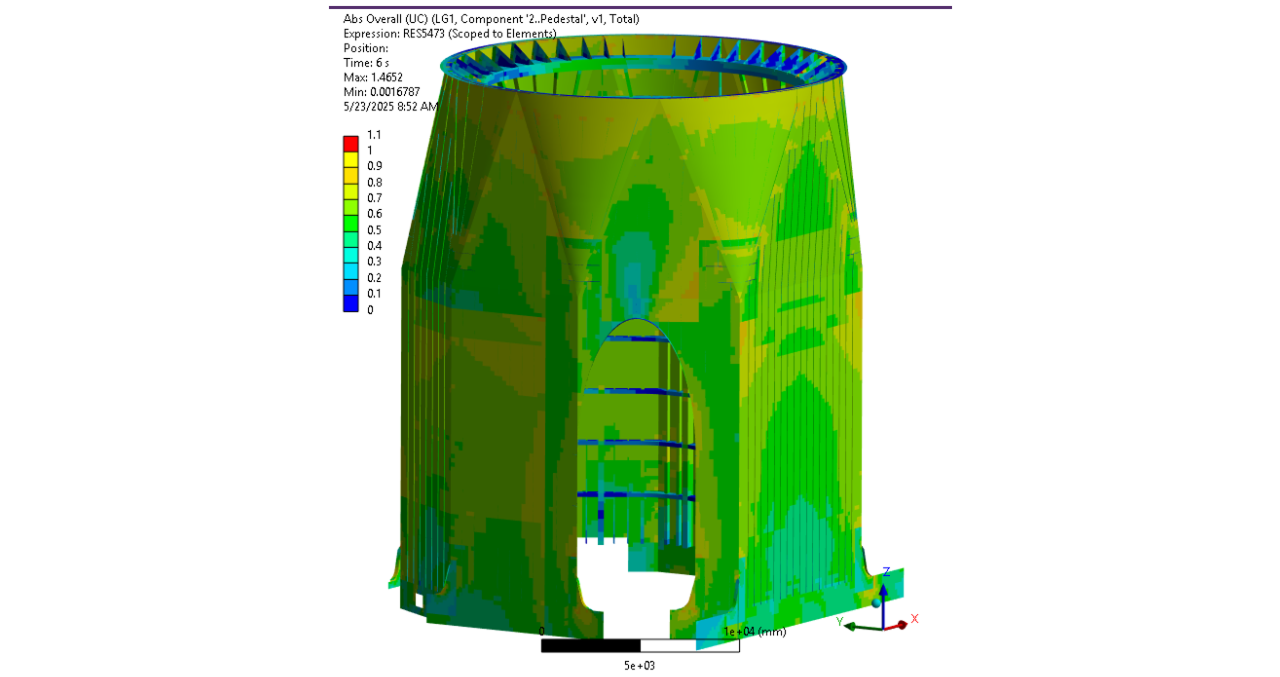
Plate yielding utilization plot generated in SDC Verifier
Buckling
Plate and stiffener buckling checks were performed for the pedestal and support structure. SDC for Ansys was used to calculate utilization values for panels and stiffeners under the governing load combinations.
The local buckling assessment confirmed that the main pedestal structure met the required buckling criteria under the defined DNV-based checks.
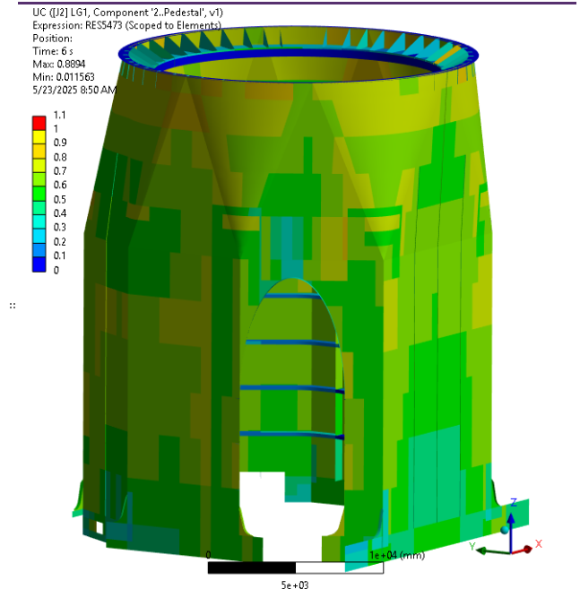
Buckling utilization of pedestal and supporting structure
Fatigue
The fatigue analysis showed that the crane pedestal fatigue life exceeds the minimum 20-year requirement for the main scantlings.
The analysis also identified local areas that need more detailed design-stage review. In particular, the connecting brackets between the crane pedestal and hull did not meet the simplified fatigue criteria and were marked for further detailed fatigue analysis. The cutouts on the main longitudinal bulkhead below the pedestal were also reserved for additional detailed-design review.
This is a useful engineering result: the primary pedestal structure passed the preliminary fatigue-life requirement, while the workflow also highlighted where local connection details need further attention before final design closure.
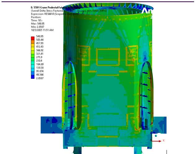
Factored stress ranges for pedestal and support structure
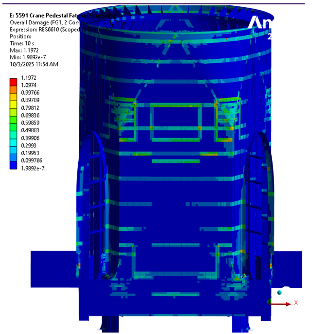
Accumulated fatigue damage for pedestal and support structure
Outcome
The analysis confirmed that the WindSetter WTIV main crane pedestal has sufficient strength to support the leg-encircling crane.
Using SDC for Ansys with ANSYS Workbench results, Friede & Goldman was able to organize a large verification scope into a structured workflow covering load combinations, yielding, buckling, fatigue, and reporting.
The final result was a clear DNV-based verification package for the crane pedestal and supporting structure, with the main strength checks satisfied and fatigue performance confirmed for the primary scantlings over the minimum 20-year design-life requirement.