


From Linear FE Screening to Nonlinear Assessment of an Offshore Vessel Under Arctic Ice Loads


2
analysis stages
2
buckling criteria checked
- Linear FE screening identified critical hull areas under ice loads.
- SDC for Femap was used for Buckling State Limit and Ultimate Strength checks.
- Nonlinear analysis was then used to assess structural behavior beyond the linear range.
- The final assessment confirmed adequate ultimate capacity and global integrity.
Offshore vessels operating in Arctic conditions can be exposed to severe localized loads caused by direct interaction with ice.
For ice-strengthened hull structures, linear finite element analysis provides an efficient first assessment of stresses, deformation, and structural stability. But when buckling becomes critical, a linear assessment may not be sufficient to understand the actual structural reserve.
In this CESAC project, the engineering team used a staged workflow combining FEMAP, the FE solver environment, and SDC for Femap to assess an offshore vessel hull under design ice loads.
The initial linear assessment and buckling verification identified localized areas with high utilization. These results triggered a geometrically and materially nonlinear analysis to investigate the structural response beyond the linear range and assess the available ultimate capacity.
Perform structural checks directly in Femap
SDC for Femap helps engineers automate structural verification, evaluate utilization and buckling results, and identify critical areas without leaving the Femap workflow.
Explore SDC for Femap
Project at a glance
- Engineering company: CESAC, Structural Specialist Consultants
- Structure: Ice-strengthened offshore vessel hull
- FE environment: FEMAP 2020.2 / FE solver
- Verification software: SDC for Femap
- SDC for Femap scope: Buckling verification
- Verification criteria: Buckling State Limit and Ultimate Strength
- ABS rules applied: ABS SVR 6.1.2/6.1.4; ABS SVR Part 6.1.2/33.3
- Analysis workflow: Linear FE screening followed by geometrically and materially nonlinear analysis
Assessing an ice-strengthened offshore vessel hull
The finite element model was developed to evaluate the structural response of the ice-strengthened hull under Arctic ice loading conditions.
The model preparation included:
- detailed mesh generation;
- material definition;
- boundary conditions;
- ice patch load application in critical hull regions;
- multiple ice load cases;
- refined shell and stiffener meshes in areas requiring more detailed assessment.
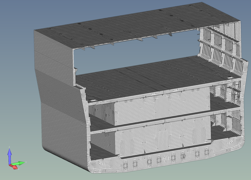
Finite element mesh of the offshore vessel hull section used for the structural assessment.
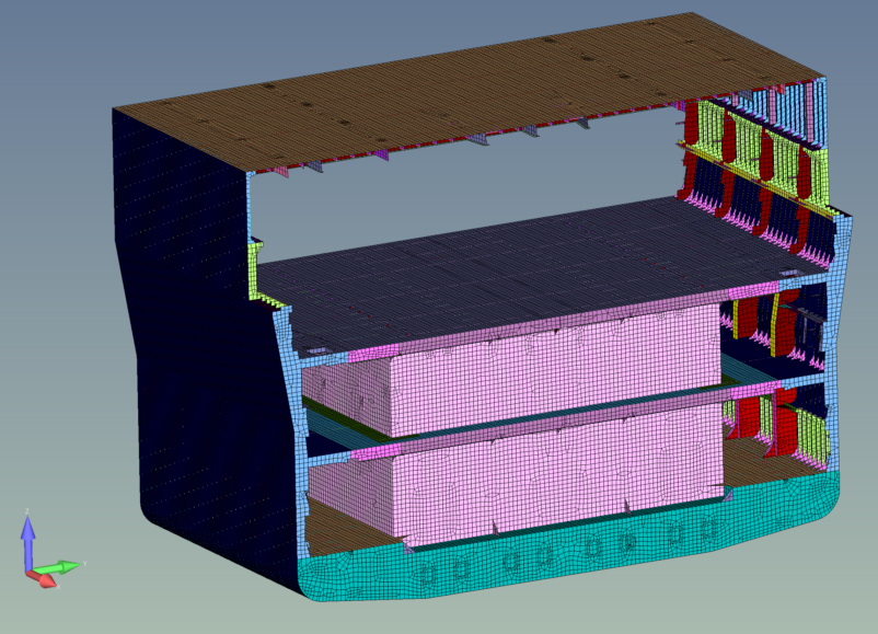
Thickness distribution of the offshore vessel hull section included in the assessment.
FEMAP 2020.2 was used for FE model preparation and the overall analysis workflow.
The initial linear FE calculations were used to assess stress distribution, deformation, and structural stability in the ice-strengthened hull areas under the applicable ice loads.
Using linear analysis as a screening step
The linear FE analysis provided the first screening of the structural response.
This made it possible to identify areas most sensitive to instability and focus the subsequent verification on the critical structural regions.
SDC for Femap was used specifically for the buckling assessment of the FE results according to the applicable ABS Rules.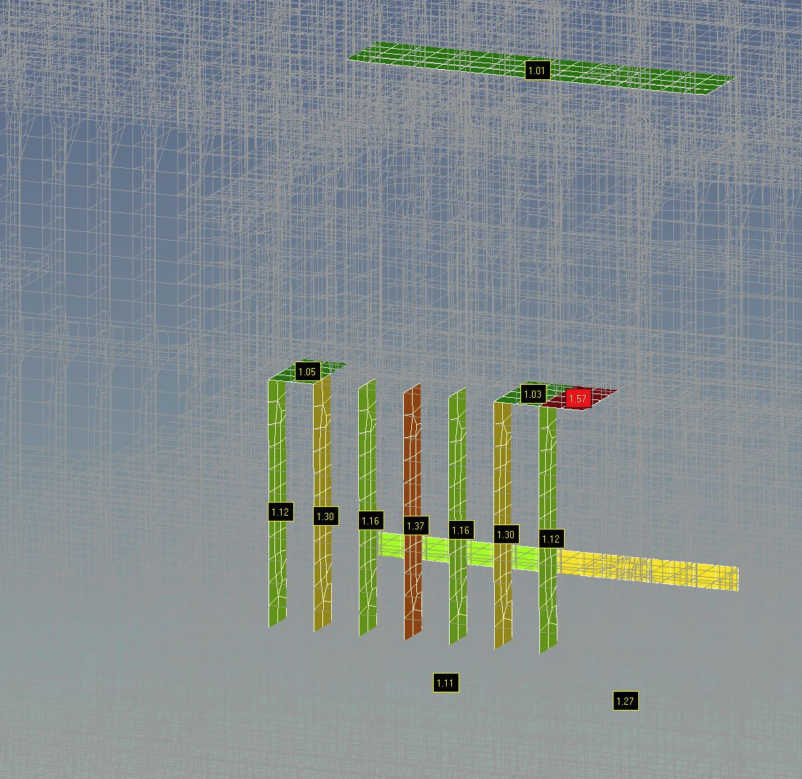
Buckling assessment in SDC for Femap showing localized high-utilization areas, including a critical result of 1.57.
The verification covered the Buckling State Limit and Ultimate Strength checks, with CESAC referencing:
- ABS SVR 6.1.2/6.1.4;
- ABS SVR Part 6.1.2/33.3.
The buckling assessment identified several localized areas with utilization close to or above the acceptable limits.
These results were important because they showed where the assumptions of the linear assessment were becoming insufficient for a reliable evaluation of the structural response.
A high utilization result can identify a critical region, but it does not fully describe how the structure behaves after deformation moves beyond the linear range.
The engineering team therefore proceeded with a more detailed nonlinear assessment.
For additional background on the mechanisms involved, see local and overall buckling.
Moving beyond the linear range
A geometrically and materially nonlinear FE analysis was performed for the midbody area.
The objective was to capture structural effects that could not be represented adequately in the initial linear assessment, including:
- large deformation effects;
- material yielding and stiffness degradation;
- local and overall buckling behavior;
- stress redistribution after yielding;
- post-buckling structural response.
The nonlinear analysis itself was performed through the FE solver environment.
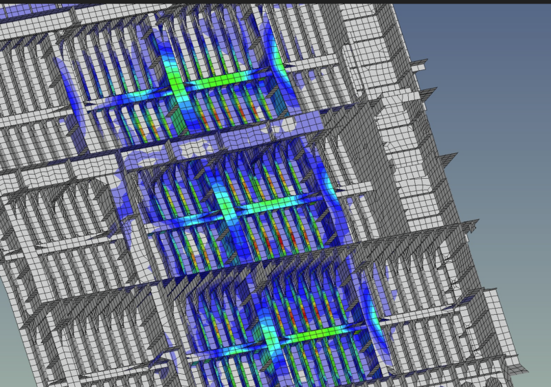
Nonlinear FE assessment of the critical hull region identified during the initial buckling verification.
SDC for Femap was not used to run the nonlinear FE analysis. Its role in this workflow was the buckling verification that helped identify the critical areas requiring further investigation.
Evaluating the structural reserve
The nonlinear assessment provided a more detailed representation of how the structure behaved under the applied design ice loads.
Localized buckling and plastic deformation were observed in the analysis.
However, these local effects did not result in a loss of overall structural integrity.
The nonlinear assessment demonstrated that the analyzed structure retained adequate ultimate capacity and global integrity under the design ice loads.
This was the key engineering outcome of the project.
The initial linear assessment and buckling verification efficiently identified the critical regions. The nonlinear analysis then provided the additional information required to understand the behavior of those regions beyond the linear range.
This is also why linear and nonlinear FEA should not necessarily be treated as competing approaches.
In this project, they served different purposes within the same verification workflow.
The role of SDC for Femap
In this project, SDC for Femap had a specific role: buckling verification of the FE results.
It was not used to perform the nonlinear FE analysis or the rule scantling verification.
The overall workflow was:
- FE model preparation in FEMAP Mesh definition, materials, boundary conditions, and ice load application.
- Linear FE analysis Initial assessment of stresses, deformation, and structural response under the design ice loads.
- Buckling verification in SDC for Femap Evaluation of Buckling State Limit and Ultimate Strength criteria and identification of localized areas with high utilization.
- Nonlinear FE analysis Detailed investigation of the critical regions, including large deformations, yielding, stress redistribution, and post-buckling behavior.
- Ultimate capacity assessment Evaluation of whether the structure retained sufficient global integrity under the applied ice loads.
This staged workflow allowed the engineering team to use linear analysis efficiently as an initial screening method while applying the more computationally demanding nonlinear analysis where it was actually required.
For a broader example of applying structural verification to ship structures, see structural verification of ship designs.
Bring structural verification into your Femap workflow
SDC for Femap helps engineering teams automate structural checks, evaluate governing utilization and buckling results, and generate verification reports directly from existing FE models.
Request a trial
Why the staged workflow matters
For complex structures subjected to severe localized loading, the objective is not simply to obtain a utilization ratio.
The real engineering question is what that result means for the behavior and capacity of the structure.
In this project:
- the linear FE analysis provided an efficient first assessment;
- the SDC Verifier buckling check highlighted the governing structural areas;
- the nonlinear analysis investigated what happened beyond the linear response;
- the final assessment demonstrated the available structural reserve under the design ice loads.
This progression from screening to deeper analysis allowed CESAC to focus detailed engineering effort on the areas where it was actually needed.