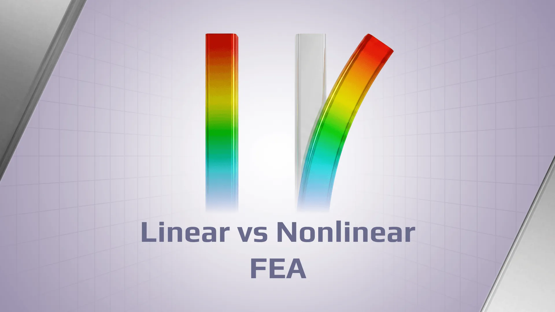
An engineer completes a linear static analysis. The model solves without difficulty; stresses and displacements look reasonable, and the verification report contains no obvious warning signs. Yet one critical question remains: do the assumptions behind the model still represent how the real structure behaves?
The decision is rarely related to whether nonlinear finite element analysis is inherently more accurate. For many structural problems, linear FEA is an appropriate and efficient approach when deformations remain small, materials remain within the intended elastic range, and load paths do not change materially. However, some modeling conditions, such as changing contact between components, may require a nonlinear analysis to accurately represent the structural response.
Problems arise when the structural response begins to alter the model’s assumptions. Large displacements can modify stiffness; materials may yield and lose linear behavior, and contact interfaces can open, close, or slide. In these situations, a linear solution may still produce plausible-looking results while no longer representing the actual structural response.
The real engineering question is therefore not linear versus nonlinear software. It is whether deformation, material response, or changing boundary conditions have altered the structure enough that the original linear model is no longer representative. Understanding where that boundary lies is essential for both reliable simulation and defensible structural verification.
What Does Linear FEA Actually Assume?
Linear Finite Element Analysis (FEA) relies on fundamental simplifications so that the relationship between applied forces and structural displacement is proportional. When those assumptions remain valid, linear analysis is efficient, reliable, and entirely appropriate. When they do not, the results can become increasingly misleading, even if the model solves without errors.
A Proportional Force–Displacement Response
For a linear static problem, the structural response is proportional to the applied load. If the load is doubled, the calculated displacements, stresses, strains, and reaction forces also double.
This behavior is represented by the familiar equilibrium equation:
K u = F
where:
K is the stiffness matrix;
u is the displacement vector;
F is the applied load vector.
The important assumption is that the stiffness matrix, K, remains constant throughout the analysis. The structure is solved around its original, undeformed geometry, and the calculated response does not alter the model itself.
Because the response is proportional, the principle of superposition applies. Individual load cases can be analyzed separately and then combined, provided the load combinations are compatible, and the assumptions of linearity remain valid.
Small Deformation Assumptions
The term small deformation is frequently misunderstood. It does not mean that displacements must be visually insignificant or remain below some universal percentage of the model dimensions.
The relevant question is whether the deformation changes the physics of the problem.
Linear analysis assumes that displacements and rotations are sufficiently small that they do not significantly alter:
the structural stiffness;
the direction of applied loads;
the load path through the structure;
the equilibrium configuration;
second-order effects, such as additional moments generated by deformation.
Linear Elastic Material Behavior
Linear FEA also assumes linear elastic material behavior. Stress and strain remain proportional and follow a straight-line relationship defined by the material’s elastic properties, such as Young’s modulus.
An equally important assumption is reversibility. If the load is removed, the material returns to its original shape without permanent deformation. For many engineering structures operating below the yield point, this assumption provides sufficiently accurate results.
Unchanging Contacts and Boundary Conditions
Linear analysis further assumes that supports, constraints, interfaces, and load application conditions remain unchanged during the entire solution.
A fixed support remains fixed, a bonded connection remains bonded, and the mechanism by which loads are transferred through the structure does not vary as deformation occurs.
However, a linear model can represent fixed or bonded interfaces, but it cannot capture :
opening or closing contacts;
separation of components;
frictional sliding;
intermittent load transfer;
changes in contact area;
compression.
What Makes an FEA Problem Nonlinear?
An FEA problem becomes nonlinear when the relationship between the applied forces and structural displacement is no longer proportional.
For this reason, nonlinear analysis typically progresses through increments. Depending on the solution method, these may be controlled by load, displacement, or arc length. After each increment, the solver iteratively seeks equilibrium between the internal forces generated by the structure and the externally applied loads.
At each load increment, the solver performs convergence checks. Convergence means that the solution has reached the predefined numerical tolerances for quantities such as force and displacement residuals. However, convergence only indicates that the numerical solution satisfies the solver criteria.
Most nonlinear structural issues originate from one or more of three sources: geometric nonlinearity, material nonlinearity, and contact or boundary-condition nonlinearity.
Geometric nonlinearity occurs when the deformed shape of the structure influences its response.
This behavior can arise from:
large displacements or rotations;
stiffness changes caused by the deformed geometry;
second-order effects, such as P–Delta behavior;
snap-through phenomena;
instability and post-buckling response.
Such behavior is particularly relevant in the following structures:
slender crane and lifting structures;
offshore frames, if they are slender;
thin-walled and plated structures;
slender columns and other compression members;
cables and suspended bridges;
flexible booms and support structures.
Material Nonlinearity
Material nonlinearity occurs when the relationship between stress and strain is no longer proportional.
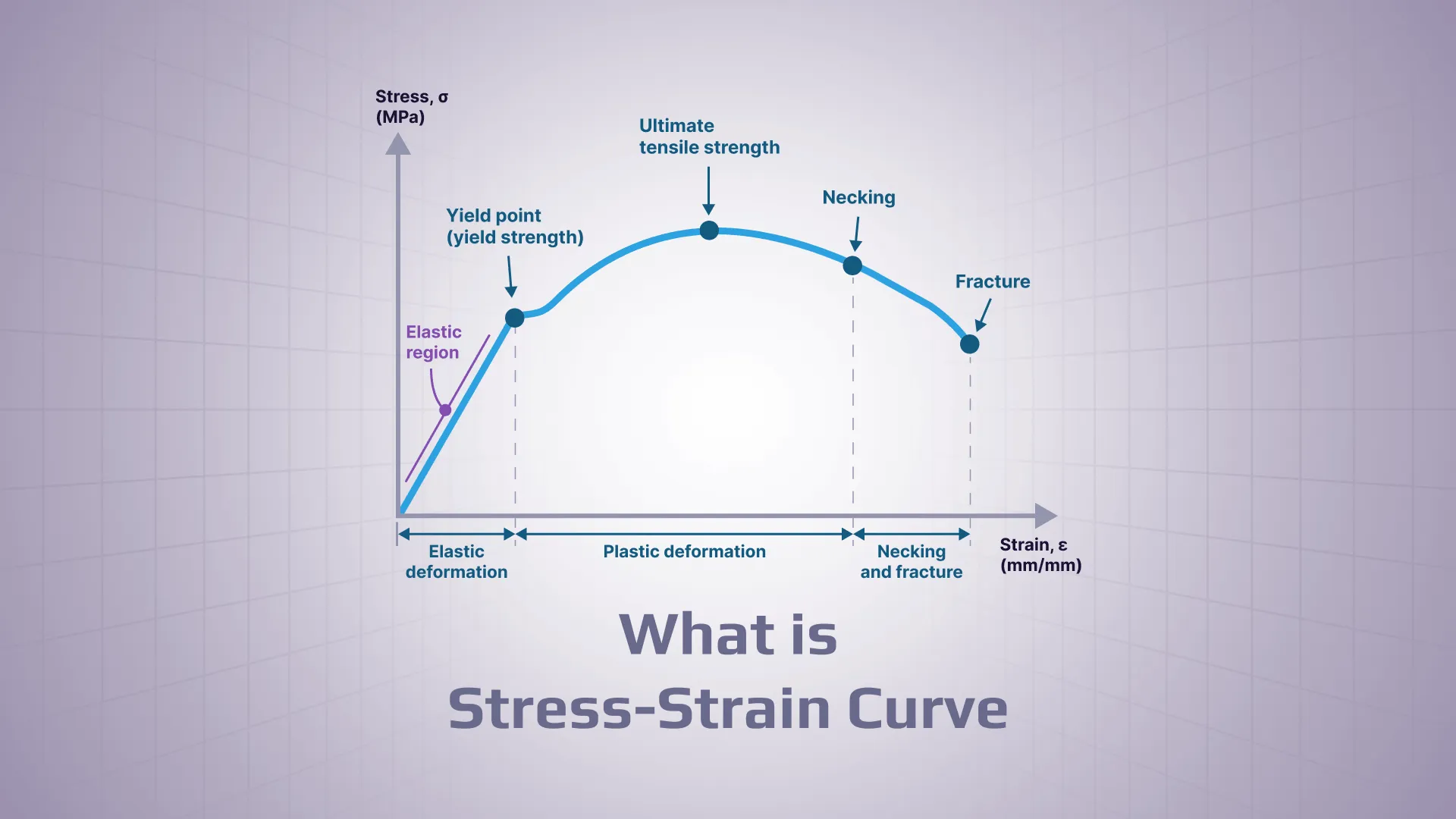
Within the elastic range, stress increases linearly with strain and the material returns to its original shape after unloading. However, once yielding begins, the material response changes. Different materials have different stress–strain relationships, and this relationship can change as the stress level increases.
For example, in structural steel, the stress–strain curve typically shows an initial elastic region, followed by yielding and plastic deformation. After yielding, steel can continue to carry additional load as plastic strain develops, with the stress increasing again due to strain hardening. Permanent strains may remain after unloading, and stresses can redistribute through the structure.
Material nonlinearity can involve:
yielding;
plastic deformation;
stress redistribution caused by plasticity;
nonlinear stress-strain relationships.
Contact and Boundary-Condition Nonlinearity
Contact and boundary-condition nonlinearity occurs when supports, interfaces, or load transfer mechanisms change during loading. Linear analysis assumes that connections remain in the same state throughout the solution.
Examples include:
gaps opening or closing;
surfaces separating and re-establishing contact;
frictional sliding;
compression-only supports;
changing support conditions;
evolving connection interfaces;
bolt or clamp load transfer mechanisms.
Image: Three sources of nonlinearity
Linear vs Nonlinear FEA – Side-by-Side Comparison
Aspect
Linear FEA
Nonlinear FEA
Geometry
Original geometry governs the solution
Geometry may update during loading
Material model
Linear elastic
May remain linear elastic or include nonlinear material behavior, depending on the problem.
Stiffness
Constant
May change between increments
Contacts
Fixed or idealized
May open, close, separate, or slide
Load application
Usually solved in one step
Applied through increments or analysis steps
Superposition
Generally valid for compatible linear cases
Generally, not valid
Solver process
Direct and relatively stable
Iterative and convergence-dependent
Computation
Faster
More computationally demanding
Main risk
Missing relevant nonlinear behavior
Using nonlinear analysis when it’s not required which takes a lot of time
Typical use
All verification based on standards
Instability, plasticity, large deformation, or evolving contact
Image: Illustrative example of linear vs nonlinear force-displacement response diagram
When Is Linear FEA Usually Enough for Steel Structures?
Stresses remain within the intended elastic range of the material;
deformations do not materially alter the load path or structural stiffness;
rotations remain consistent with the small-displacement assumption;
supports, connections, and interfaces do not change their state;
no meaningful opening, separation, sliding, or frictional load transfer occurs;
the design question does not require explicit modeling of nonlinear instability, post-buckling, or collapse behavior;
the applicable design standard is based on linear elastic analysis;
These conditions are common in practice, from stiff machinery frames and steel beams operating within the elastic range to early design comparisons and routine stress screening. Many structural standards also rely explicitly on linear elastic analysis for code verification.
Linear FEA remains widely used because it is computationally efficient, transparent, and relatively easy to validate against hand calculations and engineering judgment. When its assumptions remain representative of the real structure, a nonlinear model does not automatically provide a better answer. It simply introduces additional complexity, computational cost, and modelling decisions. The goal is therefore to use the level of analysis that the engineering problem actually requires.
Warning Signs That Linear Analysis May No Longer Be Enough
The following diagnostic questions can help you determine whether the assumptions behind linear FEA are beginning to break down.
The Deformed Shape Changes the Load Path
Does deformation influence how the loads act on the structure?
It can happen when:
an axial load develops additional bending moments due to deflection;
the direction of an applied force or pressure changes as the structure deforms;
a flexible plate or shell develops membrane action;
the structure becomes noticeably softer or stiffer during deformation.
The Expected Material Response Goes Beyond Linear Elasticity
Imagine these cases:
post-yield behavior governs the acceptability of the design;
permanent deformation is important;
plastic redistribution is part of the acceptance criteria;
the objective is to determine ultimate load or collapse capacity.
Contact Status Changes During Loading
Consider these examples:
a gap closes;
contacting surfaces separate;
friction influences load transfer;
a support carries compression but releases in tension.
Stability Is the Actual Design Question
Linear buckling analysis is useful for identifying likely buckling modes and estimating idealized critical load factors. However, many real structures are sensitive to imperfections, geometric changes, and post-buckling effects.
For these problems, a nonlinear analysis may be required. Linear buckling and nonlinear analysis serve different purposes and should not be treated as interchangeable methods.
Linear Results Are Physically Implausible
Potential warning signs include:
impossible deformation patterns;
unrealistic structural stiffness;
reaction forces that do not match the intended restraint system;
excessive stresses caused by highly idealized supports;
results that continue scaling linearly even though the real material or interface should change state.
Often, the first indication that a nonlinear effect matters is not a solver warning, but an engineering judgment that the calculated behavior no longer resembles the physical structure.
Four Structural Examples
1. Slender Member Under Compression
A slender column is subjected to an axial compressive load. As the member deflects, the axial load generates additional bending moments. These second-order, or P–Delta, effects increase deformation and stresses.
A first-order linear analysis may underestimate second-order bending moments, lateral displacement, and the resulting utilization. This can lead to a non-conservative structural assessment.
2. Thin Plate or Shell Approaching Instability
A thin-walled plate or shell structure may be sensitive to buckling even when stresses remain below yield. Linear buckling analysis can identify likely buckling modes and estimate idealized critical load factors, making it valuable for screening and understanding instability mechanisms.
However, it cannot predict how geometric imperfections, load redistribution, or post-buckling behavior influence the real structure. Evaluating these effects may require a geometrically nonlinear analysis with representative imperfections. Where yielding or ultimate capacity is relevant, material nonlinearity may also need to be included.
3. Connection with Changing Contact
A bolted connection may allow for some slippage or separation between connected plates as the load changes. Similarly, a support that works only in compression may lose contact when the applied load changes direction or becomes insufficient to maintain contact.
These situations involve changing contact conditions that can affect load transfer and structural stiffness. A nonlinear analysis requires appropriate contact definitions and validation of the resulting contact status, load distribution, and connection stiffness.
This is more aligned with the engineer’s comment because it gives two concrete examples:
bolted plates → possible slip/separation;
compression-only support → contact can be lost.
And importantly, it doesn’t imply that every bolted connection requires nonlinear analysis—only that changing contact conditions may make it necessary.
4. Local Yielding Around a Load Introduction Point
High stresses often occur near load introduction regions, supports, or geometric discontinuities. A linear analysis may show stresses above the material yield strength, but this result alone does not demonstrate plastic collapse.
The stress peak may represent a stress singularity, a small local plastic zone, or a region where limited yielding redistributes stresses without compromising the overall structure. In other cases, yielding may continue to develop into a failure mechanism.
Determining which situation applies may require nonlinear material modelling, depending on the governing standard, the acceptance criterion, and whether the local stress is physically meaningful.
Where nonlinear material analysis is used, the model should include an appropriate stress–strain curve, yield criterion, and validation of the resulting plastic deformation and stress redistribution.
How to Decide Between Linear and Nonlinear FEA
Using the following steps-checklist, you can decide whether linear assumptions remain sufficient.
Step 1: Define the Engineering Question
First, determine what you actually need to know. Is the objective:
elastic stress verification;
stiffness assessment;
stability screening;
fatigue input generation;
permanent deformation;
real contact behavior;
ultimate load capacity;
whether code checking according to standard must be done;
if linear combinations of loads are required?
The analysis type cannot be selected correctly until the required engineering conclusion is clear.
Step 2: Identify the Dominant Possible Nonlinearity
Evaluate the potential sources of nonlinearity separately:
geometry;
material behavior;
contacts;
boundary conditions.
Avoid activating every nonlinear feature at once. The model should represent the physical effects that are relevant to the engineering question.
Step 3: Start with the Simplest Defensible Model
Even when a nonlinear analysis is required, a linear baseline is often valuable. It provides:
an order-of-magnitude check;
an initial understanding of the load path;
a reference result for comparison;
a way to identify modelling errors before adding nonlinear complexity.
Step 4: Add Only the Relevant Nonlinear Behavior
Introduce only the nonlinear effects that matter for the problem being solved. For example:
activate geometric nonlinearity when second-order effects are the primary concern;
introduce a nonlinear material model when yielding governs the response;
replace bonded interfaces with evolving contact only where separation or sliding affects load transfer.
Step 5: Compare Engineering Quantities, Not Only Contour Plots
The comparison between linear and nonlinear results should focus on engineering quantities, including:
global displacements;
reaction forces;
internal forces;
load-displacement response;
analyze stresses and their direction;
check strain results;
governing utilizations where applicable;
stability behavior;
contact forces and contact status.
Step 6: Confirm That the Verification Method Accepts the Results
Finally, ensure that the model, extracted results, and design-code checks are based on compatible assumptions. A nonlinear solution, just like a linear one, does not by itself provide a design or verification answer. The results still need to be properly post-processed and compared with the requirements defined by the applicable project criteria or design standard.
Why a Converged Nonlinear Solution Can Still Be Wrong
One of the most common misconceptions in nonlinear FEA is that a converged solution is necessarily a correct one.
Numerical convergence simply means that the solver satisfied the selected convergence criteria and found equilibrium according to the specified tolerances. It does not prove that the model accurately represents the real structure or that the results are physically meaningful.
For this reason, nonlinear results always require engineering validation. Useful checks include:
Reaction and load balance: Do the reactions and applied loads satisfy overall equilibrium?
Plausible deformed shape: Does the deformation pattern make physical sense?
Load-displacement response: Does the response follow the expected structural behavior, including stiffness changes or instability effects?
Sensitivity to load increments: Do the results remain reasonably consistent when the load stepping strategy changes?
Sensitivity to convergence tolerances: Are the conclusions robust, or do they depend heavily on specific solver settings?
Mesh convergence in critical zones: Are there no singularities in point of interest?
Sensitivity to contact parameters: Do small changes in contact definitions significantly alter the response?
Realistic material data: Are the nonlinear material properties representative of the actual material behavior?
Comparison with a linear baseline: Does the nonlinear response differ for physically understandable reasons?
Comparison with hand calculations, test data, or benchmarks: Can the results be corroborated by independent evidence?
Identification of modelling artifacts: Are there signs of artificial stabilization, numerical artifacts, or other modelling assumptions influencing the solution?
Difference between Linear and Nonlinear Analysis in Structural Verification
Finite element analysis and structural verification answer different engineering questions:
FEA predicts how a structure responds under the assumptions of the model;
Structural verification determines whether members, plates, welds, bolts, connections, and other components satisfy the applicable acceptance criteria.
For this reason, the analysis method and the verification method must be compatible.
Depending on the applicable requirements, design standards such as DNV, Eurocode 3, ASME, and others may account for effects such as imperfections, eccentricities, and second-order behavior through prescribed factors, simplified methods, or specific analysis approaches. In many cases, this means that nonlinear analysis is not required. Engineers therefore need to confirm which analysis method and result quantities are appropriate for each check, and whether the assumptions behind the analysis match those of the applicable verification procedure.
This distinction becomes particularly important in nonlinear analysis. Since superposition is generally no longer valid, load combinations and result envelopes may behave differently than in linear analysis. Results should not be transferred blindly from a nonlinear solution into a code check that was developed for different assumptions.
The challenge is not only obtaining analysis results but also determining how those results should be used for verification. SDC Verifier, FEA software for structural verification, is designed specifically for this step. It allows engineers to use FEA results from its built-in Simcenter Nastran solver as well as from Ansys Mechanical, Femap, and Simcenter 3D, and combine them with automated code checks, standards compliance, and engineering reporting in a single workflow.
The final verification report should document the relevant nonlinearities, material and contact assumptions, solver approach, convergence behavior, validation activities, and acceptance methods. SDC Verifier supports this process by automatically generating engineering reports that consolidate analysis assumptions, verification results, and supporting documentation into a structured, traceable format.
How SDC Verifier Supports the Workflow
Once the appropriate analysis method has been selected, the next step is configuring the analysis and connecting the results to structural verification.
In SDC Verifier, a Job is a calculation set that contains loads, combinations, and defined calculation options. When creating a Job, you can explicitly select the required analysis type, including Linear Static and Nonlinear Static analyses.
Image: SDC Verifier interface window for choosing Jobs (Version: SDC Verifier 2026 R1)
Image: Linear static Job settings (Version: SDC Verifier 2026 R1)
A typical nonlinear workflow starts by creating a Nonlinear Static Job and defining the relevant solution settings. Depending on the problem, you can configure:
the number of load increments;
the maximum number of iterations per step;
stiffness update methods;
displacement, load, and work convergence tolerances;
solution strategies such as Full or Modified Newton–Raphson, arc-length methods, line search, quasi-Newton, and bisection techniques;
large-displacement and large-angle formulations where applicable.
During and after the solution process, SDC Verifier allows you to review both intermediate and final results. Requested result categories can include displacements, stresses, applied loads, reactions, element forces, and force balance, providing visibility into how the structure responds throughout the analysis.
The resulting model outputs can then be used in supported structural verification workflows, including model review, standards checks, result processing, and automated reporting. This allows engineers to move from analysis results to documented verification within a single environment rather than manually transferring data between multiple tools.
Also, if a nonlinear problem is solved in Femap, Ansys, or another FEA software, the results can be imported into SDC Verifier and post-processed using standards, reports, and other verification tools. Users can also develop custom formulas to post-process and compare selected results.
The exact nonlinear material models, contact formulations, instability analyses, and code-check workflows depend on the selected SDC Verifier product and the capabilities of the underlying solver. They are not necessarily supported identically in SDC Verifier Standalone, SDC for Ansys, SDC for Femap, and SDC for Simcenter 3D.
Move from FEA Results to Structural Verification
Set up linear and nonlinear static jobs in SDC Verifier, review structural results, and continue into supported standards checks and automated reporting workflows.
The best analysis method is not the most sophisticated one—it is the one that captures the behavior that actually governs the engineering decision.
Use linear FEA when its assumptions remain representative of the physical structure and are compatible with the required verification approach. In many applications, linear analysis is not a simplification but an appropriate engineering model.
Move to nonlinear FEA when deformation, material behavior, contact conditions, or instability changes the structural response in a way that affects the design conclusion. The additional complexity is justified only when those effects are relevant to the question being answered.
Do not introduce nonlinear modelling merely because the solver provides it. Equally, do not remain with a linear model simply because it solves faster.
The final responsibility is always the same: validate that the model represents the real structural behavior and that the resulting quantities are compatible with the selected verification method.
FAQ
Is nonlinear FEA always more accurate than linear FEA?
No. It can represent behavior that a linear model cannot, but only when the nonlinear inputs, solver controls, material data, contacts, and boundary conditions are appropriate and validated.
What are the three main types of nonlinearity in FEA?
Geometric, material, and contact or boundary-condition nonlinearity.
When should I switch from linear to nonlinear FEA?
When deformation changes stiffness or load paths, materials leave the intended linear range, contact conditions change, or instability and collapse behavior before yield of material are part of the engineering question.
Can linear FEA predict buckling?
Linear eigenvalue buckling analysis can estimate idealized critical loads and likely buckling modes. It does not generally capture imperfections, progressive stiffness changes, or post-buckling behavior.
Why does nonlinear FEA fail to converge?
Common causes include unstable physical behavior, incorrect constraints, unrealistic contacts, unsuitable material data, large load increments, poor mesh quality, and inappropriate solver controls.
Can nonlinear FEA results be used for structural code checks?
Sometimes, but this depends on the selected standard, limit state, analysis method, result type, and implementation of the check. Compatibility must be confirmed rather than assumed.
Should every FEA model be run both linearly and nonlinearly?
No. A nonlinear comparison is useful when a plausible source of nonlinearity could affect the engineering decision. It is unnecessary when the linear assumptions are clearly valid.