Differences between ANSI/AISC 360-22 and ANSI/AISC 360-10. Chapters D to H
In the world of engineering, precision and safety are paramount. The ANSI/AISC (American National Standards Institute/American Institute of Steel Construction) standards have long been the foundation for designing steel structures across various industries, including civil engineering, heavy lifting, offshore and maritime, and others. Among these standards, ANSI/AISC 360-22 Specification for Structural Steel Buildings is the latest iteration, bringing essential updates to structural steel design. This article provides a concise comparison of ANSI/AISC 360-22 and its 2010 counterpart, focusing on the following key chapters implemented in SDC Verifier:
- D. Design of members for tension,
- E. Design of members for compression,
- F. Design of members for flexure,
- G. Design of members for shear,
- H. Design of members for combined forces and torsion.
The changes discussed in this article have been integrated into our latest software release SDC Verifier 2023 R2. Our software now fully supports the mentioned above updated ANSI/AISC 360-22 standard chapters for all cross-sections that were supported in the previous version, although we’re planning to add support for more shapes in the coming releases.
Chapter D – Design of Members for Tension
The most important changes in this chapter are the ones made in Section D3 “Effective Net Area” Table D3.1 “Shear Lag Factors for Connections to Tension Members” and the addition of a new reduction factor Cr , to the equation (D5-2). Other than this there are some minor changes regarding the clarification of some symbols and User Notes, the revision of the diameter of pin holes for pin-connected members, and the added description of usage of lacing on the open-sides of built-up tension members.
The changes made to the Shear Lag Factors table are worth paying more attention to, as they are defined as one of the five characteristics in regards to this standard implementation in SDC Verifier, which means that they have to be defined by the user. Overall, the major part of this table remains the same with the following exceptions:
- Plate members and tension members that transmit tensile load through longitudinal welds only have been removed from Case 2,
- Case 4 has been expanded to include angles, channels with welds at the heels, tees and W-shapes with connected elements; the equation for calculating U and the example figure have been updated to address longitudinal welds of unequal length; a footnote [a], has been added on how to calculate l,
- Case 5 has been updated to clarify that the gusset plate is connected through slots in the HSS,
- Cases 5 and 6 (round HSS and rectangular HSS with single concentric gusset plate) have been combined into Case 5, and the determination of the shear lag factor has been revised for both,
- Case 6 is now rectangular HSS with two side gusset plates, and the shear lag factor has been revised.
The design tensile strength (LRFD), \[ϕ_t P_n\], and the allowable tensile strength (ASD), \[P_n/\Omega_t\], according to the limit state of shear rupture now includes a new reduction factor, Cr, for shear rupture on pin-connected members which depends on the difference between the diameter of the pin and the diameter of the hole.
| AISC 360-10 | AISC 360-22 | ||
| \[P_n=0.6F_u\ A_sf\] |
(D5-2) | \[P_n=0.6C_r\ F_u\ A_sf\] |
(D5-2) |
Chapter E – Design of Members for Compression
Throughout the whole chapter the following terminology has been changed: “critical stress”, and the associated symbol, Fcr, have been revised to “nominal stress”, and the symbol, Fn; effective length is now defined as Lс and a User Note has been added to show that Lс can be determined by methods other than using the effective length factor K; uniform compression has been changed to axial compression and unbraced length to effective length. Additionally minor changes have been made to definitions of some variables and some User Notes edited for clarity.
The first major change appears in Section E4, which title has been changed by adding Single Angles – now “Torsional and Flexural-Torsional Buckling of Single Angles and Members without Slender Elements”. This Section now clearly states that it applies to all doubly symmetric members without slender elements when the torsional unbraced length exceeds the lateral unbraced length and for single angles with \[b/t\ >0.71\sqrt{E/F_y\ }\]. These changes resulted in the removal of 2 equations – previous (E4-2) and (E4-3) – and moving most of the remaining equations between subsections. We won’t describe these changes in-depth, as the addition of the single angle cross section is currently in development.
Section E5 “Single Angle Compression Members” has been reworded to clarify when flexural-torsional buckling needs to be considered. This change corresponds to the first change in Section E4, but has also been reversed to highlight when not to consider flexural-torsional buckling. Two requirements for use of this Section have been moved to the main body from individual Sections E5(a) and E5(b): Lc/r ≤ 200 and the ratio between the long leg and short leg dimensions must be less than 1.7.
Changes in Section E6 “Built-up Members” are mostly revisions of definitions and other clarifications. The title of Section E6.2 has been changed from “Dimensional Requirements” to “General Requirements” and reorganized from paragraphs into a list (a) through (e).
Section E7 “Members with Slender Elements” includes another major change. This Section has been revised in its entirety to treat stiffened and unstiffened elements the same. The approach was changed completely – now it’s more similar to the AISI approach. Variables Qs and Qa are no longer used in the Specification. Equation (E7-1) has been revised to reflect that an effective area is now used in place of a reduced stress as in 2010. For this reason, equations (E7-2) and (E7-3) have been deleted from this Section. A User Note on calculating Ae has been added.
| AISC 360-10 | AISC 360-22 | ||
|---|---|---|---|
\[P_n=F_cr\ A_g\] | (E7-1) | \[P_n=F_n\ A_e\] | (E7-1) |
When \[\frac{KL}{r}\le4.71\sqrt{\frac{E}{QF_y}}\] \[(or \frac{QF_y}{F_e} \le2.25)\] \[F_cr=Q[0.658^{\frac{QF_y}{F_e }} ] F_y\] | (E7-2 | When \[\lambda\le\lambda_r\ \sqrt{\frac{F_y}{F_n}}\] \[b_e=b\] | (E7-2) |
When \[KL/r>4.71\sqrt(E/(QF_y\ ))\] \[(or \frac{QF_y}{F_e} >2.25)\] \[F_cr=0.877F_e\] | (E7-3) | When \[\lambda>\lambda_r\ \sqrt{\frac{F_y}{F_n}}\] \[b_e=b(1-c_1\ \sqrt{\frac{F_el}{E_n}})\ \sqrt{\frac{F_el}{E_n}}\] | (E7-3) |
2022 User Note: The effective area Ae, may be determined by deducting from the gross area Ag, the reduction in area of each slender element determined as (b-be)t.
The names of the subsections have been changed accordingly – Subsection E7.1 from “Slender Unstiffened Elements, Qs” to “Slender Element Members Excluding Round HSS” and Subsection E7.2 from “Slender Stiffened Elements, Qs” to “Round HSS”.
Equation (E7-3) introduces several new variables – some calculated from newly added equations (E7-4) and (E7-5), and some taken from Table E7.1 “Effective Width Imperfection Adjustment Factors c1 and c2”. This whole new procedure has been implemented in a fully automated way, so we’re not going into any more detail to keep the article concise, since it won’t require any additional input from the user.
Subsection E7.2 introduces two additional equations used to calculate the effective area Ae, for a round HSS cross section – these have been fully implemented as well.
Chapter F – Design of Members for Flexure
The size of Chapter F exceeds the possibilities to discuss all the minor changes in detail in this article, so we will briefly go over all of its sections and delve a little deeper only on the major differences. The sections are as follows:
- F1. General Provisions – minor changes to the structure of this chapter; the section addressing the lateral-torsional buckling modification factor has been separated into a new subsection F1(c); the User Note has been expanded to clarify that the commentary contains additional equations for calculating Cb – this may be important for some users in specific cases as the Cb factor is another characteristic that has to be defined by the user in our implementation,
- F2. Doubly Symmetric Compact I-shaped Members and Channels Bent about their Major Axis – the User Note on compactness has replaced 65 ksi with 70 ksi in the last statement on web compactness limits,
- F3. Doubly Symmetric I-shaped Members with Compact Webs and Noncompact or Slender Flanges Bent about their Major Axis – no significant changes,
- F4. Other I-shaped Members with Compact or Noncompact Webs Bent about their Major Axis – the equation for the effective radius of gyration rt, (F4-11) in Lateral-Torsional Buckling calculations has been revised and is now implemented as the previous User Note version,
- F5. Doubly Symmetric and Singly Symmetric I-shaped Members with Slender Webs Bent about their Major Axis – minor changes to improve the clarity of some subsections, no other significant changes,
- F6. I-shaped Members and Channels Bent about their Minor Axis – only a slight adjustment of a multiplier in equation (F6-4) from 0.69 to 0.70,
- F7. Square and Rectangular HSS and Box Sections – major changes, equations (F7-2) and (F7-6) have been revised to a format more consistent with the flange local buckling equations for the nominal flexural strength of I-shapes, a new Subsection F7.3(c) has been added for the treatment of sections with slender webs and compact or noncompact flanges, a new Subsection F7.4 “Lateral-Torsional Buckling) has been added to provide a treatment of LTB for HSS and box sections, using a similar approach to that which is used for other sections,
- F8. Round HSS – no changes,
- F9. Tees and Double Angles Loaded in the Plane of Symmetry – the scope of some the subsections was increased to include double-angle legs, otherwise all the subsections were significantly reorganized, but since Tees are another shape that is currently in development, we won’t go any further into these changes,
- F10. Single Angles – minor changes regarding the organization of this section including the removal of equation (F10-5), as equation (F10-4) is now applicable to unequal leg angles, but similarly as above Single Angles are currently in development,
- F11. Rectangular Bars and Rounds – equation (F11-1) was split into two (F11-1) and (F11-2) to differentiate the nominal flexural strength for rectangular bars and for rounds, subsection F11.2 “Lateral-Torsional Buckling” was reorganized for clarity,
- F12. Unsymmetrical Shapes – no changes,
- F13. Proportions of Beams and Girders – no significant changes.
Regarding the changes in Subsections F7.2 “Flange Local Buckling” and F7.3 “Web Local Buckling” the equations are presented below.
|
AISC 360-10 | |
| \[M_n=M_p-(M_p-F_y\ S)(3.57\ \frac{b}{t_f}\ \ \sqrt{\frac{F_y}{E}}-4.0)\le M_p\] |
(F7-2) |
| \[M_n=M_p-(M_p-F_y\ S)(0.305\ \frac{h}{t_w}\ \ \sqrt{\frac{F_y}{E}}-0.738)\le M_p\] |
(F7-5) |
|
AISC 360-22 | |
| \[M_n=M_p-(M_p-F_y\ S)(\frac{\lambda-\lambda_{pf}}{\lambda_{rf}-\lambda_{pf}\ })\le M_p\] |
(F7-2) |
| \[M_n=M_p-(M_p-F_y\ S)(\frac{\lambda-\lambda_{pw}}{\lambda_{rw}-\lambda_{pw}\ })\le M_p\] |
(F7-6) |
We won’t discuss the equations added in the new Subsection F7.4 “Lateral-Torsional Buckling” in detail since it’s a very similar approach as in the subsections dedicated to LTB for different shapes. You can find out more about the implementation of this subsection by looking at the dedicated to it Check ID9 in the AISC 360-22 Members standard in our software.
Below you can see the utilization factor results for the bending check in the old (AISC 360-10) and new (AISC 360-22) version of the standard for a rectangular HSS cantilever beam with a high depth-to-width ratio.
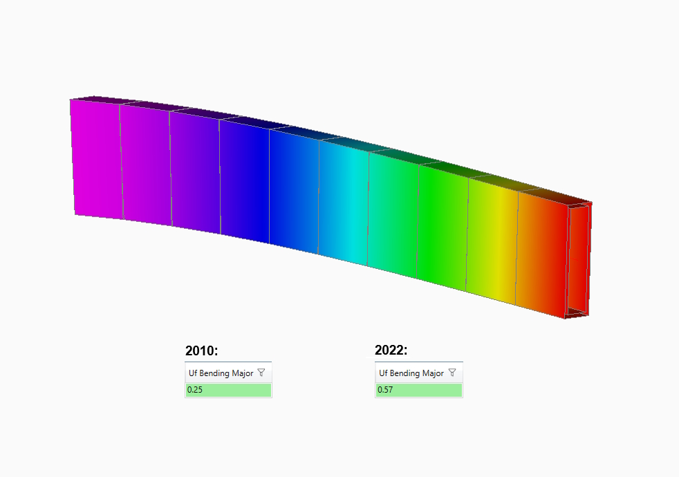
According to the User Note in cases such as these, where rectangular HSS members with a high depth-to-width ratio are bent about their major axis, significant reduction in flexural strength due to lateral-torsional buckling can be observed. The 2010 Specification doesn’t take LTB into consideration for rectangular HSS members, which results in a significantly underestimated utilization factor.
Chapter G – Design of Members for Shear
Section G3 “Tension Field Action” was moved into two subsections of Section G2 now named “I-shaped Members and Channels”, so one section was removed as the effect and the other renumbered and in many cases renamed. For a general overview you can see the structure of this chapter compared below.
| AISC 360-10 | AISC 360-22 |
| The chapter is organized as follows: G1. General Provisions G2. Members with Unstiffened or Stiffened Webs G3. Tension Field Action G4. Single Angles G5. Rectangular HSS and Box-Shaped Members G6. Round HSS G7. Weak Axis Shear in Doubly Symmetric and Singly Symmetric Shapes G8. Beams and Girders with Web Openings | The chapter is organized as follows: G1. General Provisions G2. I-Shaped Members and Channels G3. Single Angles and Tees G4. Rectangular HSS, Box Sections, and Other Singly and Doubly Symmetric Members G5. Round HSS G6. Doubly Symmetric and Singly Symmetric Members Subjected to Minor-Axis Shear G7. Beams and Girders with Web Openings |
There have been some minor changes in this chapter regarding the terminology, where in the 2022 version “major” and “minor” are preferred to “strong” and “weak” from the 2010 version when describing an axis, also some reorganization and clarifications have been made.
In Section G2 “I-shaped Member and Channels” the entire approach for non-tension field action design has been revised, but the approach for design with tension field action has not changed. The determination of shear strength for built-up I-shapes has been revised. A new paragraph has been added summarizing the applicability of Sections G2.1, G2.2, and G2.3.
One of the major changes is that the coefficient Cv used in this Section has been renamed Cv1 and as a result the h/tw parameters and associated equations have been changed, and Equation (G2-5) has been removed.
In Subsection G2.1(b)(2), the maximum value of kv has been raised to 5.34 and the limit of h/tw has been removed. The statement specifying kv for stems of tee shapes has been moved to Section G3, which now applies to tee stems. Equation (G2-5) (previously Equation (G2-6)) has been revised with the maximum value of 5.34 and the a/h limit removed.
| AISC 360-10 | AISC 360-22 | ||
|---|---|---|---|
\[k_v=5+\frac{5}{(a/h)^2}\] \[=5\ when\ a/h>3.0\ or\ a/h\ >[\frac{260}{(h/t_w\ )}]^2\] | (G2-6) | \[k_v=5+\frac{5}{(a/h)^2}\] \[=5.34\ when\ a/h>3.0\] | (G2-5) |
In the new Section G2.2 “Shear Strength of Interior Web Panels with \[a/h\ \le\ 3\] Considering Tension Field Action” former Equations (G3-1) and (G3-2) have been moved into this Section as Equations (G2-6) and (G2-7). Additionally, new variable Cv2 has been defined in this Section. Equations for determining Cv2 are similar to Equations (G2-3), (G2-4) and (G2-5) in the 2010 Specification.
Another major change is that in sections G3 “Single Angles and Tees”, G4 “Rectangular HSS, Box Sections, and Other Singly and Doubly Symmetric Members” and G6 “Doubly Symmetric and Singly Symmetric Members Subjected to Minor-axis Shear” the applicable equations for the shapes governed by these Section have been added, so they no longer all reference the equation (G2-1) as they did in the 2010 Specification.
| AISC 360-10 | AISC 360-22 | ||
| \[V_n=0.6F_y\ A_w\ C_{v}\] |
(G2-1) | \[V_n=0.6F_y\ A_w\ C_{v1}\] |
(G2-1) |
| \[V_n=0.6F_y\ bt C_{v2}\] |
(G3-1) | ||
| \[V_n=0.6F_y\ A_w\ C_{v2}\] |
(G4-1) | ||
| \[V_n=0.6F_y\ b_{f}t_{f} C_{v2}\] |
(G6-1) | ||
Chapter H – Design of Members for Combined Forces and Torsion
Throughout this chapter, the separate lists of defined symbols for LRFD and ASD have been condensed into one list of definitions for both LRFD and ASD, replacing the terms “design strength” and “allowable strength” with “available strength”. Other than that, some definitions of parameters have either been updated or added, mostly minor changes to improve the clarity.
The only major change appears in Section H3 “Members Subjected to Torsion and Combined Torsion, Flexure, Shear, and/or Axial Force” where the equation H3-6 has been revised to include required-to-available flexural strength ratios for both major- and minor-axis bending. A requirement is added that “Vr/Vc shall be taken as the larger value for the x- or y-axis.”
|
AISC 360-10 |
AISC 360-22 | ||
| \[(\frac{P_r}{P_c} +\frac{M_r}{M_c} )+(\frac{V_r}{V_c} +\frac{T_r}{T_c} )^2\le1.0\] |
(H3-6) | \[(\frac{P_r}{P_c} +\frac{M_{rx}}{M_{cx}}+\frac{M_{ry}}{M_{cy}} )+(\frac{V_r}{V_c} +\frac{T_r}{T_c} )^2\le1.0\] |
(H3-6) |
Conclusion
In conclusion, this article has provided a concise overview of the key changes introduced in the ANSI/AISC 360-22 standard compared to ANSI/AISC 360-10. We hope it has given you a general understanding of the modifications made in the chapters addressing tension, compression, flexure, shear, and combined forces with torsion.
In SDC Verifier, the structural engineer can perform member buckling checks according to three generations of AISC standards:
At SDC Verifier, we always make sure that our solutions comply with the tests and examples provided in the standard and periodically publish AISC 360-10 Design Examples Benchmarks.
However, for a deeper dive into selected major differences and their practical implications on structural steel design and calculation outcomes, stay tuned. In the near future, we will be publishing a follow-up article that delves further into the intricacies of these changes and presents their influence on the results in a few given examples.
