In crane and lifting-structure analysis, wind is not a single horizontal force applied uniformly across the model.
The resulting wind action depends on the wind profile over height, the crane operating location and applicable design condition, the exposed structure, member orientation, and the drag coefficients used to calculate the load. A lattice boom, machinery house, platform, and tubular brace do not present the same projected area or require the same coefficient assumptions.
SDC Verifier uses the defined wind profile and drag coefficients to calculate and apply wind loads to the selected FEA elements. EN 13001 and F.E.M. 1.001 coefficients can be applied automatically to recognized 1D beam elements, while members modeled with plates or solids require manually assigned coefficients.
A model can produce reasonable-looking stress contours while still being based on an incorrect wind-load definition. This article explains how to define, apply, and review wind loads in SDC Verifier.
Set Up Crane Wind Loads
Apply and review wind loads directly in your crane FEA workflow with SDC Verifier.
Step 1 — Define the Crane Condition Before Applying Wind
The same crane can have different governing wind cases because its exposed area, load path, stiffness, and support reactions change with configuration.
Start by defining whether the crane is operating or parked. An operating case may include a lifted load, a specific boom angle, and a trolley position that shifts both the vertical load and the wind-induced moment. A parked or out-of-service case may have no payload but a different boom position, slewing lock condition, or wind exposure that becomes critical for stability or support reactions.
The boom or jib position matters because it changes the elevation, projected area, and center of gravity of the structure. A luffed boom, a horizontal jib, and a lowered boom do not expose the same geometry to the same wind direction, and they can also affect crane stability under the combined loading condition.
Trolley, payload, and hook positions also need to match the intended load case. Moving the trolley toward the boom tip can increase the overturning effect and change which members, connections, or supports govern. Even when the payload does not add wind area, it changes the structural response to the combined loading condition.
Check the slewing orientation as well. A crane may react very differently when the boom is aligned with the wind than when the wind acts across it. The governing direction is often linked to the relationship between wind direction, boom orientation, and the support layout.
Support or foundation conditions must represent the actual setup. Outrigger positions, rail supports, pedestal stiffness, foundation restraints, and tie-down conditions all affect how wind loads are transferred into the supporting structure.
Finally, confirm which equipment and attachments are included in the model. Machinery houses, cabins, platforms, counterweights, handrails, maintenance equipment, and other attachments can materially change the exposed area and load distribution. Include only the components present in the condition being assessed, and ensure their wind coefficients are defined appropriately.
Do not define wind as a generic load before deciding which actual crane configuration the model represents.
Step 2 — Define the Wind Profile and Ground Reference
Before applying wind to the model, define how the wind action changes with elevation and where that elevation is measured from.
A wind profile is not only a list of pressure or velocity values. It must be mapped to the model using the selected global vertical direction and zero-height reference. If these are defined inconsistently with the crane model, the correct pressure or velocity values can be applied at unintended elevations.
Wind load setup in SDC Verifier: vertical direction, wind vector, application approach, ground level, and height-dependent pressure profile
Set the Vertical Axis
The vertical axis tells SDC Verifier how to read element elevation when applying wind pressure or velocity by height.
In many crane models, the global Z-axis is vertical. However, this should be verified rather than assumed. Imported models, rotated assemblies, local coordinate systems, and non-standard model orientations can all make a different axis or direction relevant.
Before defining the wind load, verify the model orientation in the global coordinate system. SDC Verifier uses the selected global direction to determine element height for the wind profile; it does not use each element’s local coordinate system for this purpose. The selected vertical direction should therefore correspond to the actual elevation of the crane structure, from the support level to the boom tip and elevated equipment.
Set the Zero-Height Reference
The zero-height reference defines where SDC Verifier starts measuring height for the wind profile in the model.
It does not define the design wind speed or wind condition. Those values must come from the crane operating location, applicable wind zone, site data, governing standard, or project-specific requirements.
In the wind-load setup, the zero-height reference is used to map the defined pressure or velocity profile to the model elevations. Set it consistently with the project datum, such as rail level, foundation level, pedestal base, or another defined reference elevation.
The reference should not be selected only because it is convenient in the model coordinates. For tall cranes, an inconsistent zero-height reference can apply the wind profile to the wrong elevation range and change the calculated load on boom sections, gantries, machinery platforms, elevated cabins, and lattice members.
Define Pressure or Velocity by Height
SDC Verifier supports two ways to define a height-dependent wind profile:
Pressure by height — enter wind pressure values directly at defined elevations.
Velocity by height — enter wind velocity values at defined elevations and specify the air density used to calculate pressure.
Use the method that matches the available project input and the governing design basis. The values should come from the applicable standard, site data, client specification, or approved wind-action calculation.
For example, a wind profile can be entered as a set of values over height:
Height above zero reference
Wind velocity
0 m
24 m/s
10 m
26 m/s
20 m
28 m/s
40 m
31 m/s
60 m
33 m/s
These values are illustrative only. In a real project, the profile must be replaced with the approved wind input for the crane operating location, wind zone, and design condition.
Step 3 — Set Wind Direction and Load-Application Approach
Wind direction affects more than the sign of the applied load. It changes the projected area of members and equipment, the distribution of forces across the structure, the global overturning moment, and the local utilization of individual members, connections, and supports.
SDC Verifier lets you define the wind direction using the global coordinate system. You can select a main global direction, create wind loads at defined angular increments, or specify a custom wind vector manually.
Use a main global direction when the required wind case aligns with the model axes. Use angular increments when several wind directions need to be checked, for example every 30° or 45° across a defined range. Use a manually defined vector when the wind direction must follow a specific project angle or when the crane orientation does not match the main global axes.
The wind-load direction is not defined from the local coordinate system of individual elements. Local element axes may still be relevant for member orientation and drag-coefficient calculation, but the wind vector itself is defined globally in the wind-load setup.
After defining the direction, select the load-application approach that matches the element type and the engineering assumption behind the model.
Projected Area applies wind according to the area of the element projected toward the wind direction. This approach is commonly relevant when the exposed area changes with member orientation.
Velocity Component uses the component of wind velocity relative to the element orientation. It can be useful where the load definition needs to reflect how the element is aligned with the wind.
Normal to Face applies pressure normal to the selected surface. This is generally relevant for plate- or surface-based geometry where the exposed face is explicitly represented in the model.
No single approach is correct for every crane model. The selection should match the modeled geometry, the available wind input, and the design assumption being checked. Beam members, shell structures, enclosed equipment, and simplified structural representations may require different treatment.
Before continuing, review the selected direction against the crane configuration. Confirm that the wind vector represents the intended physical case and that the expected surfaces or member groups are exposed to the load.
Step 4 — Apply Standard-Based Drag Coefficients
SDC Verifier lets engineers select drag coefficients according to EN 13001 or F.E.M. 1.001 for recognized beam members, then review how those values were selected before applying the wind load.
SDC Verifier supports projected-area, velocity-component, and normal-to-face wind-load application approaches.
When F.E.M. 1.001 Is Useful
F.E.M. 1.001 is an older crane standard that has largely been replaced by EN 13001 in new projects. However, it is still sometimes used when evaluating existing cranes, legacy calculations, or older projects where F.E.M. 1.001 was part of the original design basis.
In SDC Verifier, the F.E.M. 1.001 drag-coefficient workflow can be applied automatically to recognized 1D beam elements. The coefficient selection is based on the available beam-member data, such as cross-section shape, member length, and slenderness.
This automatic workflow applies to beam elements only. If the same physical member is modeled with plate or solid elements, the coefficient must be assigned manually.
Typical beam-member cases include:
lattice boom members;
truss members;
diagonal and horizontal braces;
gantry legs;
boom and jib chords;
other crane members represented as 1D beam elements.
The main value is not that F.E.M. 1.001 is preferred for new crane projects, but that engineers can still apply and review this coefficient logic when the project or existing crane documentation requires it.
F.E.M. 1.001 drag-coefficient review based on beam-member geometry and slenderness in SDC Verifier.
When EN 13001 Is Useful
EN 13001 is useful when the crane project is developed around EN 13001 requirements and the engineering team needs the drag-coefficient selection to follow the same design context.
In SDC Verifier, the EN 13001 option considers beam-member geometry and the relationship between the wind direction and the member axes as part of the coefficient-selection workflow.
This can be relevant when:
the crane is designed or verified under EN 13001 requirements;
the project team needs to document how wind coefficients were selected within the crane design workflow;
the wind direction relative to beam-member axes must be checked explicitly;
multiple crane orientations or wind directions are being evaluated.
Selecting EN 13001 coefficients does not, by itself, demonstrate full EN 13001 compliance for the crane. The complete verification still depends on the applicable load cases, combinations, safety factors, design assumptions, and checks required for the project.
EN 13001 drag-coefficient review in SDC Verifier, including member properties and coefficients for 0° and 90° wind orientations.
What to Review Before Applying Coefficients
Do not treat standard-based coefficient selection as a black box. Before applying the wind load, review the member groups and the data used for the calculation.
Check that:
the expected 1D beam members were recognized correctly;
the cross-section shape, member length, slenderness, and orientation used for coefficient selection match the actual model;
the selected drag coefficients are reasonable for the member geometry and wind direction;
each coefficient group includes the intended beam elements;
the beam-member orientation and coefficient selection match the real physical exposure of the structure;
members modeled with plates or solids are not treated as automatically recognized beam members;
manually assigned coefficients are used where the automatic beam-member workflow does not apply.
This review is especially important for imported models, simplified crane models, and structures that combine beam members with shell or solid geometry.
Standard-based drag coefficients improve consistency, but they do not remove the need to check whether the model represents the real exposed structure.
Product Note: EN 13001 Implementation
EN 13001 drag-coefficient calculation is available in SDC Verifier as a Beta feature. In the current workflow, coefficients are calculated for 0° and 90° between the wind vector and the member’s local axes.
For critical project cases, check the current product documentation and confirm that the implemented workflow matches the project requirements and the wind directions being assessed.
Step 5 — Handle Plates, Solids, and Non-Standard Geometry
Standard-based drag-coefficient selection has a clear boundary. The EN 13001 and F.E.M. 1.001 workflows apply to beam members that have recognized cross-section data in the model.
Shell and solid elements use the coefficient values assigned for plates or solids. This is relevant where the model includes plate structures, enclosed geometry, or detailed solid components rather than beam members with defined cross-sections.
Typical examples include:
machinery houses;
operator cabins;
counterweights;
enclosed housings;
equipment covers;
box-type fabricated structures;
plate-dominated platforms or panels;
non-standard members that do not fit the recognized beam-member workflow.
For these components, define drag coefficients separately based on the actual geometry and the engineering basis for the load case. SDC Verifier allows custom coefficient values to be assigned to a selected group of elements, so the wind-load model can reflect project-specific assumptions instead of forcing all geometry into the same beam-member rule.
Custom drag coefficients can be assigned using user selections, components, materials, properties, or groups.
Use custom coefficients only when their basis can be documented. The source may be a project specification, an approved calculation, wind-tunnel or test data, a governing design standard, or another verified engineering method.
A custom coefficient is not a workaround for an uncertain model. It should be traceable to an engineering assumption or source.
Before applying the load, check that the custom selection includes the intended geometry and does not overlap incorrectly with beam members already using EN 13001 or F.E.M. 1.001 coefficients. This avoids double-counting exposed area or applying inconsistent assumptions to the same structural component.
Step 6 — Check Multiple Wind Directions
The direction that produces the largest total wind force is not necessarily the direction that governs the structural design. A broadside wind case may create the largest projected area, while an oblique direction may produce a more critical load path through the boom, bracing system, supports, or local connections.
Why One Direction Is Rarely Enough
Different wind directions can govern different checks.
For one direction, the highest response may be global boom stress. For another, the governing result may be buckling in a slender brace, uplift at a support, local stress near a connection, or a displacement limit at the boom tip.
This is especially relevant for cranes with:
asymmetric machinery or counterweight arrangements;
non-symmetrical support layouts;
luffed booms or offset jibs;
different trolley positions;
rotating superstructures;
attachments that add exposed area on one side of the model.
The critical direction depends on the crane geometry, operating condition, support arrangement, and the response being evaluated. Do not assume that the direction with the largest resultant wind force is also the direction with the highest utilization.
Create a Wind-Direction Sweep
In SDC Verifier, create separate wind loads across the direction range that needs to be assessed.
Define the starting wind direction.
Set the required angular range.
Select an angular step.
Create separate wind loads for each direction in the sweep.
Add the generated wind cases to the relevant crane load combinations.
Compare the governing result for each required check type.
Set a custom wind vector, direction range, and angular increment to generate separate wind-load cases.
The selected range and increment should follow the project requirements and the expected structural behavior. A crane with regular geometry and clear symmetry may require fewer directions than a crane with an offset boom, complex attachments, or asymmetric support conditions.
The purpose is not to generate as many cases as possible. It is to use enough directions to identify the governing response with confidence.
When reviewing the results, compare more than total wind force. Check which direction governs:
boom stress;
member buckling utilization;
support reactions or uplift;
local stress near connections;
global or local displacement;
any other project-specific verification result.
Step 7 — Review the Applied Wind Load Before Solving
Before using wind cases in stress, buckling, fatigue, or deflection checks, review the load definition itself.
This step is where many model errors can be found before they affect the structural results. A wind load may solve without warnings even when the wrong elements are selected, the profile is referenced from the wrong level, or the applied force does not match the intended crane condition.
Review the wind load in the model and, where available, in the report. Check the selected elements, coefficient source, projected area, resultant force, and center of applied force before moving on to verification.
A reasonable-looking stress contour is not evidence that the wind load itself was defined correctly.
Review total applied area, projected area, and the center of applied forces before running structural checks.
Pre-Solve Checklist
Confirm the following before running the structural checks:
Is the selected vertical axis consistent with the actual crane elevation?
Is the zero-height reference set consistently with the model datum and intended wind profile?
Does the selected wind profile match the crane operating location, applicable wind zone, standard, site data, or approved project input?
Does the pressure or velocity profile match the approved project input?
Is wind applied only to the intended structural and non-structural components?
Are the expected beam members recognized correctly?
Are EN 13001 or F.E.M. 1.001 coefficients applied where they are appropriate?
Do plates, solids, machinery housings, cabins, and other non-standard components have documented custom coefficients where required?
Has more than one wind direction been assessed where the crane geometry or project requirement calls for it?
Does the total projected area match the exposed structure represented by the model?
Does the total resultant force have a reasonable magnitude and direction?
Is the center of applied force consistent with the height and distribution of the exposed geometry?
Are all required wind cases included in the intended load combinations?
The review should also confirm that there is no overlap between selections using standard-based beam coefficients and selections using custom plate, solid, or equipment coefficients. Overlapping selections can apply wind twice to the same geometry or create inconsistent assumptions within one load case.
Step 8 — Add Wind Loads to Crane Load Combinations
A wind load should not be checked as an isolated structural action. It must be combined with the crane condition the model is intended to represent.
Depending on the case, this can include self-weight, lifted load, trolley or hoisting effects, inertia, slewing position, support configuration, and the relevant safety factors and load groups required by the project standard.
For example, a wind case on a parked crane may be combined mainly with self-weight, support conditions, and out-of-service requirements. An operating case may also require the lifted load, trolley position, boom configuration, movement-related actions, and the applicable load factors.
The correct combination depends on the crane type, operating condition, governing standard, and project design basis.
Do not add wind to every combination by default. Add it where the design situation and governing standard require it, then verify that the intended wind direction and crane configuration are included in the final set of checks.
Worked Example — Reviewing Wind Definition on a Crane Model
This example shows how wind-load definition can be reviewed on a crane model before structural verification. The goal is not to identify a universal governing wind direction, but to check whether the applied wind setup is consistent with the crane geometry, member exposure, and intended load direction.
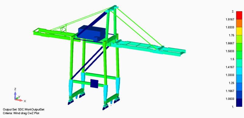
The first step is to review the drag-coefficient plots. In SDC Verifier, wind drag coefficients can be visualized on the model, making it easier to check whether the coefficient distribution matches the physical structure. This is especially useful for crane models where different members have different cross-section shapes, lengths, orientations, and exposure to wind.
Wind drag coefficients CwY plotted on the crane model to review coefficient distribution across structural members.
Wind drag coefficients CwZ plotted on the crane model to check coefficient variation for another wind-related direction.
The CwY and CwZ plots show how drag coefficients are distributed across the crane for different wind-related directions. These views help engineers verify whether the selected coefficients are reasonable for the corresponding member groups and whether the beam-member orientation used in the calculation matches the real structure.
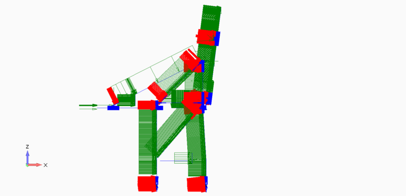
The next step is to review the applied wind directions. The Wind X and Wind Y views show how the wind load is applied for different global directions. Comparing these plots helps confirm that the selected wind direction creates the intended load pattern on the crane model before the case is used in structural checks.
Wind load applied in the global X direction, showing the load pattern on the crane structure.
Wind load applied in the global Y direction, showing the load pattern for an alternative global wind direction.
Where available, additional physical validation can provide useful context. A wind tunnel visualization can help illustrate airflow behavior around the crane geometry, but it should be treated as supplementary engineering evidence. It does not replace the wind-load definition, coefficient assignment, or verification workflow in the FEA model.
Together, these views help answer a practical pre-solve question: does the wind-load definition appear physically reasonable before the model is checked for stress, buckling, support reactions, displacement, or stability?
Final Takeaway
Wind loading should be verified before the structural results are trusted.
In SDC Verifier, engineers can define a wind profile, apply EN 13001 or F.E.M. 1.001 drag coefficients to recognized beam elements, assign manual coefficients where needed, check multiple wind directions, and review the applied load before running verification checks.
This makes the wind-load setup easier to control, review, and document as part of the crane FEA workflow.
Review Wind Loads Before Solving
Use SDC Verifier to apply and review wind loads directly in your crane FEA model. Start a trial or request a demo with your own crane structure.