The real structures normally consist of many different elements, which are joined together in different ways depending on the configuration, e.g. by welds, rivets, or bolts.
All these connection types are providing the load transferring from one structural element to another, performing its intended design functionality and remaining an important part of the structure.
Most structural failures are caused by poorly designed connections, so it’s extremely important to verify them according to the appropriate standards to ensure safety in the future.
Bolts are no exception. Bolted joint analysis is an important part of FEA engineering.
In this article it’s shown how easy the Bolts and Threaded parts can be verified according to AISC 360-10 standard (Chapter J3. specification) directly within your favorite CAE package, like Ansys, Femap, Simcenter 3D.
SDC Verifier is made on top of these programs and can automatically extract the internal forces from the 1D elements (i.e. bolts) of the FEA model so that the following checks can be quickly done directly in your simulation environment:
- Tensile and Shear Strength of Bolts and Threaded parts
- Tensile force per bolts is compared with allowable bolt tensile strength;
- Shear force per bolts is compared with bolt shear capacity;
- Combined tension and shear in Bearing-Type connections
- The required tensile stress per bolts is compared with modified nominal tensile stress, which include the effects of bolt shear stress;
- The available bolt shear stress of the fastener shall equal or exceed the required shear stress;
- High-Strength bolts in Slip-Critical connections
- The required bolt shear stress is compared with available slip resistance;
- Bearing strength at bolt holes
- The required bolt shear stress is compared with available bearing strength at the bolt holes;
A lot of details prescribed by AISC 360-10 standard are read out of your FEA model and further used in the formulas as variables for the automatic calculations of other parameters required for bolts connection checks, for instance as shown in the example below where the bolts M24 are verified:
Bolt stress area (both shear and tensile stress area of a bolt) in the checks is based on the bolt diameter, which is automatically read out of the property, although the user has the possibility to override it if required.
Note: be aware of the bolt spacing requirements given in section J3 when setting up your own values of bolt diameter (see also AISC Steel Construction Manual.)
15.. Bolts_M24
| Property | Value | Property Shape |
|---|---|---|
| Type / Elements | Beam / 154 | 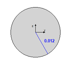 |
| Material | 12..Bridge girders_detailed | |
| Mass [kg] | 29.8 | |
| Gravity Center [m] | [15.2; 10.6; 20.0] | |
| Area, [m2] | 4.524e-04 | |
| l1, [m4] | 1.629e-08 | |
| l2, [m4] | 1.629e-08 | |
| l12, [m4] | 0 | |
| Torsion Contrast, [m4] | 3.254e-08 | |
| Y Shear Area, [m2] | 4.009e-04 | |
| Z Shear Area, [m2] | 4.009e-04 | |
| Nonstructural Mass, [kg] | 0 | |
| Perimeter, [m] | 0.1 | |
| Warping Constant, [m6] | 0 | |
| Y Neutral Axis Offset A, [m] | 0 | |
| Z Neutral Axis Offset A, [m] | 0 | |
| r [m] | 0.0120 |
With the help of Rule-Based Selector, you can create the user-defined selections of bolts to be checked, most quickly and conveniently by using all available items: based on the materials, properties, element types, and so on.

Bolts are permitted to be installed to the snug-tight condition, which is defined as the tightness required to bring the connected plies into firm contact.
All high-strength bolts specified on the design drawings to be used in pretensioned or slip-critical joints shall be tightened to a bolt tension not less than that given in Table J3.1 or J3.1M of AISC 360-10.
SDC Verifier takes 70% of the minimum bolt tensile strength by default for these preloading bolts.
Although in our example it is equal to 205kN for M24 bolts, there is also an option to set up your own specific value if required.
| TABLE J3.1M Minimum Bolt Pretension, kN* |
||
|---|---|---|
| Bolt Size, mm | Group A (e.g., A325M Bolts) | Group B (e.g., A490M Bolts) |
| M16 | 91 | 114 |
| M20 | 142 | 179 |
| M22 | 176 | 221 |
| M24 | 205 | 257 |
| M27 | 267 | 334 |
| M30 | 326 | 408 |
| M36 | 475 | 595 |
| *Equal to 0.70 times the minimum tensile strength of bolts, rounded off to nearest kN, as specified in ASTM specifications for A325M and A490M bolts with UNC threads. | ||
Nominal bolt shear strength by default is taken as 56.3% or 45% of the minimum tensile strength of bolts according to Table J3.2, while nominal bolt tensile strength by default is 75%:
| Table J3.2 Nominal Strength of Fasteners and Threaded Parts, ksi (MPa) |
||
|---|---|---|
| Description of Fasteners | Nominal Tensile Strength, Fnt, ksi (MPa) [a] | Nominal Shear Strength in Bearing-Type Connections, , Fnt, ksi (MPa) [b] |
| A307 bolts | 45 (310) | 27 (188) [c] [d] |
| Group A (e.g., A325) bolts, when threads are not excluded from shear planes | 90 (620) | 54 (372) |
| Group A (e.g., A325) bolts, when threads are not excluded from shear planes | 90 (620) | 68 (457) |
| Group B (e.g., A490) bolts, when threads are not excluded from shear planes | 113 (780) | 68 (457) |
| Group B (e.g., A490) bolts, when threads are not excluded from shear planes | 113 (780) | 84 (579) |
| Threated parts meeting the requirement of Section A3.4, when threads are not excluded from shear planes | 0.75Fu | 0.450 Fu |
| Threated parts meeting the requirement of Section A3.4, when threads are not excluded from shear planes | 0.75Fu | 0.563 Fu |
| [a] For high-strength bolts subject to tensile fatigue loading, see Appendix 3. [b] For end loaded connections with a fastener pattern length greater than 38 in. (965 mm). Fnv shall be reduced to 83.3% of the tabulated values. Fastener pattern length is the maximum distance parallel to the line of force between the centerline of the bolts connecting two parts with one faying surface. [c] For A307 bolts the tabulated values shall be reduced by 1% for each 1/16 in. (2 mm) over 5 diameters of length in the grip. [d] Threads permitted in shear planes. | ||
After these and many other details are automatically taken into account, both methods of bolt checks prescribed by AISC 360-10 – ASD and LRFD, can be executed just with few clicks.
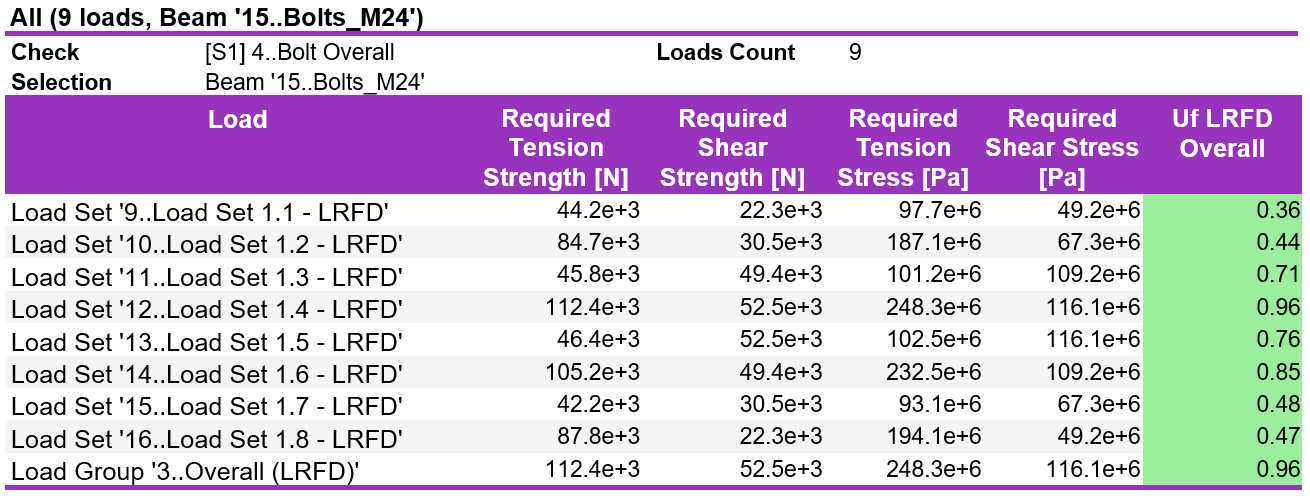
The outcomes of checks are presented by the Utilization factor (UF), which shows the ratio between the calculated stress and allowable stress per each bolt!
As known, AISC 360-10 standard prescribes a lot of load cases to be checked for both methods depending on the load types and different influencers, so it’s very handy to check the results based on the Load Group, which show the worst (absolute maximum) values of outcomes over the all load combinations in 1 picture!
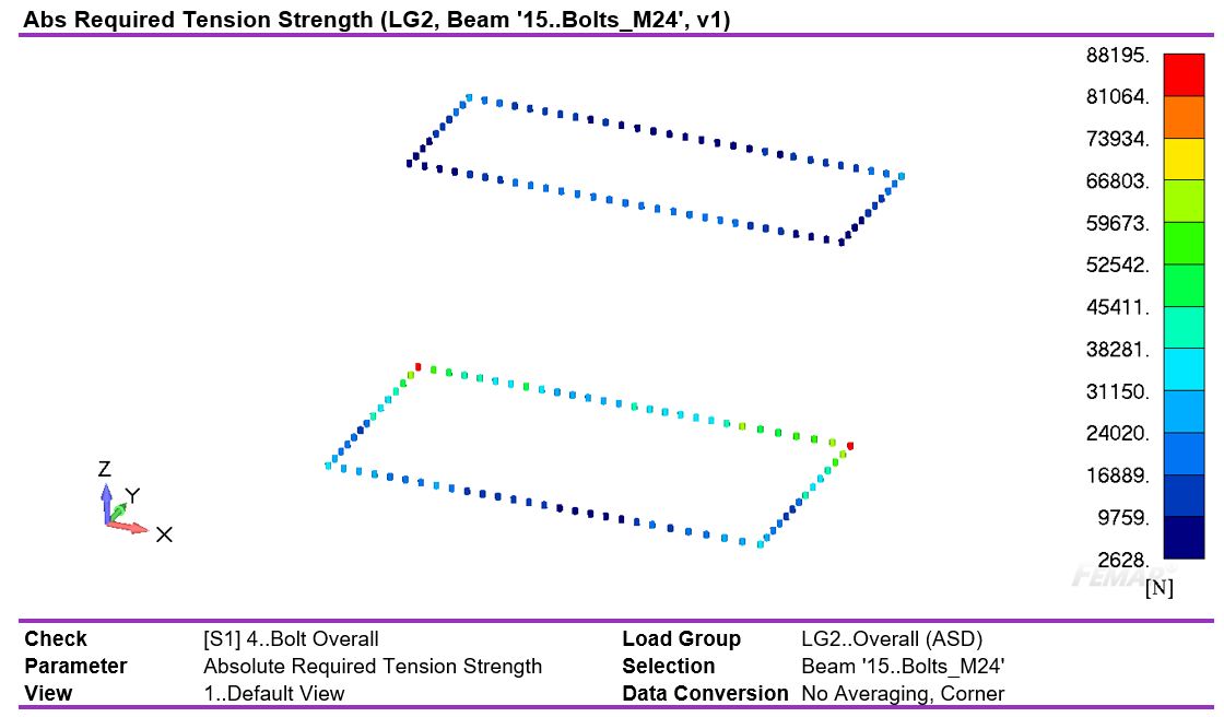
Both checks are based on the required bolt tensile strengths and bolt shear strengths, which can be also shown on the plots:
NB: The same approach with appropriate Load Groups for different methods is applied.
Required Tension Strength
Required Shear Strength
As in the other bolt checks in SDC Verifier according to EN 1993-1-8 (2005) standard, the extensive tables over the different parameters can be created, as well as the complete results overview with automatic reporting:
Last, but not least, are the specific user requirements, which can be quite different compared to the popular industry standards (Eurocode 3, AISC, EN13001, FEM 1.001 etc.). With SDC Verifier it is possible to create your custom bolt checks and take all these details into account.
Conclusion
SDC Verifier enables verification of bolts according to AISC360-10 standard directly within your favorite software (Ansys, Femap, Simcenter 3D). Any specific user requirements can be easily taken into account, while very detailed automatic reporting will make the results overview clear and save a lot of effort for you!


