Offshore Platform Design: API RP 2A & ISO 19902 (Practical Guide)
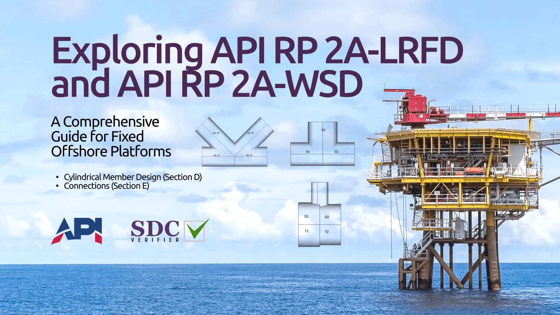
American Petroleum Institute’s (API) Recommended Practices (RP) 2A-LRFD and 2A-WSD standards provide the framework for the design, analysis, and construction of offshore structures, covering from the individual structural members to the complex network of connections that hold them together.
We’ll navigate through the intricate details of Load and Resistance Factor Design (LRFD) and Working Stress Design (WSD), exploring their core principles, their specific applications to cylindrical members and connections, and the unique challenges posed by pile design.
We’ll also examine how these standards interact with other industry benchmarks, such as the AISC specifications.
API RP 2A-LRFD: Load and Resistance Factor Design – Core Principles
API RP 2A-LRFD embodies a probabilistic approach to structural design known as Load and Resistance Factor Design (LRFD).
This methodology fundamentally shifts away from the traditional allowable stress design (ASD) by introducing the concept of factored loads and factored resistances.
In essence, LRFD recognizes the inherent variability and uncertainty in the loads a structure experiences and its capacity to resist those loads.
In the LRFD framework, loads (e.g., wind, wave, current, dead load, live load) are amplified by load factors greater than 1.0. These factors are statistically derived to account for the likelihood of loads exceeding their nominal values.
Conversely, the resistance of structural elements (e.g., yield strength, buckling capacity) is reduced by resistance factors less than 1.0. These factors reflect the potential for material properties to be less than their specified minimums or for fabrication tolerances to introduce weaknesses.
The core principle of LRFD is to ensure that the factored load effects on a structure do not exceed its factored resistance. Mathematically, this is expressed as:
Σ (Load Factor * Load) ≤ Σ (Resistance Factor * Resistance)
By applying these factors, LRFD provides a more rational and consistent approach to safety compared to ASD. It allows engineers to explicitly account for the variability in loads and resistances, leading to more reliable and robust designs.
Multiple Load Combinations
Offshore platforms are subjected to a complex interplay of loads, including environmental loads (wind, wave, current), operational loads (deck equipment, helicopter landing), and gravity loads (self-weight, stored materials).
The magnitudes and combinations of these loads can vary significantly depending on the specific location, season, and operational conditions of the platform.
To address this complexity, API RP 2A-LRFD specifies a series of load combinations that must be considered in the design process.
These combinations are based on statistical analysis of historical data and engineering judgment, and they are designed to capture the most critical scenarios that the platform is likely to encounter throughout its service life.
Some of the key load combinations specified in API RP 2A-LRFD include:
- Strength Load Combinations: These combinations are intended to ensure that the platform has sufficient strength to resist extreme loads, such as those encountered during a 100-year storm event.
- Service Load Combinations: These combinations are intended to ensure that the platform functions properly under normal operating conditions, with acceptable levels of deformation and vibration.
- Fatigue Load Combinations: These combinations are intended to ensure that the platform can withstand the cumulative effects of cyclic loading over its service life, preventing fatigue failure.
Cylindrical Member Design (Section D)
Specific Design Requirements
Section D of API RP 2A-LRFD provides a comprehensive framework for the design of steel cylindrical members, a fundamental building block of offshore platforms.
These members are subjected to a complex interplay of axial, bending, and shear forces, as well as internal and external pressures. The standard addresses these challenges by outlining specific requirements for:
- Material Properties: Minimum yield and tensile strength requirements are specified for the steel used in cylindrical members.
- Geometric Limits: API RP 2A-LRFD sets limits on the thickness, diameter-to-thickness ratio (D/t), and slenderness ratio (KL/r) of cylindrical members.
- Load and Resistance Calculations: The standard provides detailed equations for calculating the factored axial, bending, and shear capacities of cylindrical members.
- Combined Load Effects: Procedures are outlined for evaluating the interaction of axial, bending, and shear forces, ensuring that the combined effects do not exceed the factored capacity of the members.
- Special Considerations: Additional requirements are provided for members subjected to external pressure, local loads, and fatigue loading, ensuring that the design is robust and can withstand the diverse loading conditions encountered in offshore environments.
Limitations of API RP 2A-LRFD
While API RP 2A-LRFD well-established standard, it’s important to be aware of its limitations:
- Scope: The standard is primarily focused on steel cylindrical members and may not be directly applicable to other types of structural elements used in offshore platforms (e.g., non-tubular members, concrete structures).
- Material Limitations: The standard’s applicability is limited to certain steel grades with specific yield strength ranges. For higher strength steels or other materials, additional considerations or supplementary guidelines may be required.
- Geometric Limitations: The standard imposes restrictions on the thickness, D/t ratio, and slenderness ratio of cylindrical members. These limits may not be suitable for all design scenarios, particularly those involving large-diameter or thin-walled members.
SDC Verifier Implementation
The SDC Verifier software streamlines the design process by automating many of the complex calculations and checks required by API RP 2A-LRFD.
The image shows the settings dialog box in SDC Verifier for customizing the parameters of API RP 2A-LRFD (1st, 1993)
The software’s intuitive interface allows engineers to input the geometric and material properties of cylindrical members, as well as the applied loads. The software then automatically performs the following:
- Capacity Calculations: Calculates the factored axial, bending, and shear capacities of the members according to the equations specified in the standard.
- Combined Load Checks: Evaluates the interaction of axial, bending, and shear forces to ensure that the combined effects are within the allowable limits.
- Geometric Checks: Verifies that the thickness, D/t ratio, and slenderness ratio of the members meet the requirements of the standard.
- Reporting: Generates detailed reports summarizing the design results, including the factored loads, factored capacities, utilization ratios, and any potential code violations.
Connections (Section E): The Linchpin of Structural Integrity
Section E of API RP 2A-LRFD provides a comprehensive framework for the design of these critical connections, with a particular focus on tubular joints.
The Criticality of Connection Design
Connections are the points of greatest stress concentration in any structure. In the harsh offshore environment, they are subjected to cyclic loading from waves, currents, and wind, as well as static loads from the platform’s weight and operational activities.
A poorly designed connection can be the weak link in the chain, leading to premature failure and potentially catastrophic consequences. Therefore, meticulous attention to connection design is essential for ensuring the safety, reliability, and longevity of offshore platforms.
Types of Connections in Offshore Platforms
Tubular joints are the most common type of connection used in offshore platforms due to their inherent efficiency in transferring loads and their compatibility with the cylindrical members prevalent in these structures.
These joints are formed by welding or bolting together intersecting tubular members, creating a complex three-dimensional geometry.
The behavior of tubular joints under load is influenced by a multitude of factors, including the geometry of the joint, the material properties, the welding details, and the applied loads.
API RP 2A-LRFD classifies tubular joints into several categories based on their geometry and loading conditions:
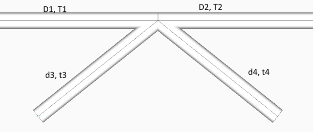
- T-, Y-, and K-joints: These simple joints are formed by the intersection of two or three members at a single node. They are primarily subjected to axial loads and in-plane bending moments. A typical T-joint configuration is illustrated below, where D1, T1 and D2, T2 represent the diameter and thickness of the chord members, while d3, t3 and d4, t4 represent the diameter and thickness of the brace members.
- X- and DT-joints: These more complex joints involve the intersection of four or more members at a single node. They can experience a combination of axial loads, in-plane and out-of-plane bending moments, and torsional moments.
SDC Verifier’s Joint Check
The SDC Verifier software offers a powerful Joint Check feature that significantly simplifies and expedites the verification of tubular joint designs.
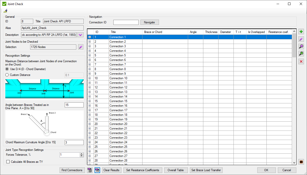
The SDC Verifier interface, as shown, provides an intuitive way for engineers to set up and customize the joint check process based on their specific model and requirements.
- Automatic Connection Recognition
The software intelligently identifies all potential tubular joints in the platform model, saving engineers valuable time and effort.
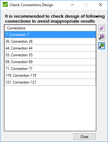
After automatic connection recognition, SDC Verifier may present a dialog box, as shown below, highlighting connections that require manual review due to potential complexities or non-standard configurations.
2. Load Transfer Considerations
For joints where a smaller diameter brace intersects a larger diameter chord, especially in the presence of a can or gusset plate, SDC Verifier automatically accounts for load transfer effects. This is crucial, especially under compression loading, as it can significantly influence the joint’s capacity. The engineer can also manually adjust load transfer settings if needed, as shown in the image below. In this interface, the engineer can specify whether load transfer should be considered for each brace member and adjust the effective length of the brace as needed.
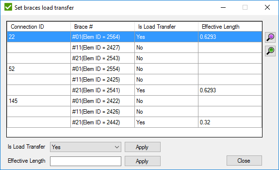
The interface where engineers can manually set the load transfer status (Yes/No) for specific brace members and adjust their effective lengths.
3. Overlapping Joint Handling
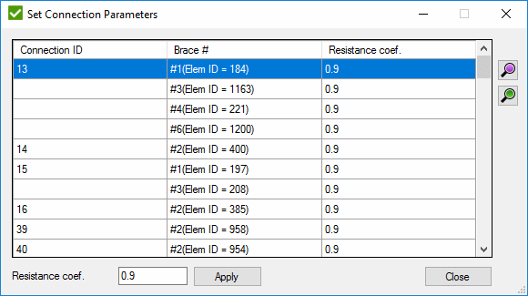
When two or more braces overlap at a joint, the “Set Braces Overlapping” dialog box, as shown below, allows engineers to identify the overlapping braces, specify their status as overlapped or not, and adjust the resistance coefficient accordingly.
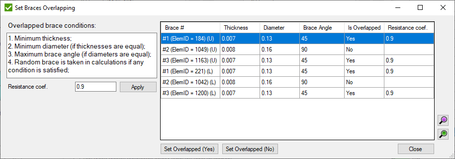
The image illustrates where engineers can specify if braces overlap and adjust the resistance coefficient accordingly.
And engineers can then indicate whether each brace is overlapped or not and adjust the resistance coefficient for the weld accordingly.
4. Effective Length Calculations
Upon completion of the joint check analysis, SDC Verifier presents a detailed table of results, as shown below. This table allows engineers to assess the adequacy of each joint based on various criteria, such as stress ratios, geometric parameters, and material properties.
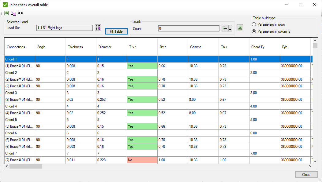
detailed table of joint check results
5. Comprehensive Reporting
The software generates detailed reports summarizing the results of the joint checks, including the applied loads, the joint capacities, the utilization ratios, and any potential code violations. This provides engineers with valuable insights into the performance of the connections and allows them to identify any areas that require further attention.
Check out our practical guidance and step-by-step instructions on how to use the software for joint check analysis.
The Importance of Effective Length Calculations
The effective length of a brace member is the length over which it is free to buckle under compressive loading. This length is typically less than the physical length of the member due to the restraint provided by the surrounding structure.
Accurate determination of the effective length is crucial for ensuring the stability of brace members and preventing buckling failure.
The SDC Verifier software employs sophisticated algorithms to automatically calculate the effective length of each brace member, taking into account the geometry of the joint, the stiffness of the connected members, and the boundary conditions.
Read more: Problems of Floating offshore wind plants verification according to industry standards
API RP 2A-WSD: Working Stress Design – Core Principles
API RP 2A-WSD, representing the Working Stress Design (WSD) methodology, is elegantly simple: ensure that the stresses induced in a structural element under service loads remain below its allowable stresses.
This is a deterministic approach where the nominal (unfactored) loads are directly compared to the allowable stresses, which are typically fractions of the material’s yield or ultimate strength.
Mathematically, the WSD principle can be expressed as:
Stress (induced) ≤ Allowable StressThis straightforward approach has been widely used in the engineering community for decades due to its intuitive nature and ease of calculation. However, it’s important to understand its underlying assumptions and limitations.
WSD vs. LRFD: A Comparative Analysis
While both WSD and LRFD aim to ensure structural safety, they differ in their fundamental philosophies and approaches.
| Feature | WSD | LRFD |
|---|---|---|
| Load Representation | Unfactored (nominal) loads | Factored loads (amplified by load factors) |
| Resistance Representation | Allowable stresses (fractions of material strength) | Factored resistances (reduced by resistance factors) |
| Safety Philosophy | Implicit safety factors embedded in allowable stresses | Explicit safety factors applied to loads and resistances |
| Complexity | Relatively simple calculations | More complex calculations due to load and resistance factors |
| Applicability | Well-established for conventional structures | More versatile for complex structures and extreme loading conditions |
| Conservatism | Tends to be more conservative, potentially leading to overdesign | Generally less conservative, allowing for more optimized designs |
WSD’s simplicity makes it a convenient tool for preliminary design and hand calculations. However, its implicit safety factors can lead to overly conservative designs, especially when dealing with complex structures or extreme loading scenarios.
LRFD, on the other hand, offers a more nuanced and flexible approach by explicitly accounting for the variability and uncertainty in loads and resistances.
This allows for more accurate assessment of structural reliability and enables engineers to optimize designs for specific performance objectives.
However, the complexity of LRFD calculations often necessitates the use of specialized software tools, such as SDC Verifier, to streamline the analysis process.
In the context of offshore platform design, both WSD and LRFD have their merits. API RP 2A-WSD provides a well-established framework for the design of conventional platform components under normal operating conditions.
However, for critical components or extreme loading scenarios, the LRFD approach of API RP 2A-LRFD may be more appropriate, as it allows for a more rigorous assessment of structural safety and reliability.
API RP 2A-WSD: Design Requirements
API RP 2A-WSD lays out a comprehensive set of design requirements for fixed offshore platforms, covering a wide range of structural elements and loading conditions. Some of the key provisions include:
- Member Design: The standard provides detailed equations for calculating the allowable stresses for various types of members, including beams, columns, braces, and plate girders. These equations consider the material properties, geometric properties, and loading conditions of each member.
- Connection Design: The standard addresses the design of various types of connections, such as welded and bolted joints. It provides guidance on the selection of appropriate connection details, the calculation of connection strengths, and the verification of connection adequacy under different load combinations.
- Load Combinations: API RP 2A-WSD specifies a set of load combinations that must be considered in the design process. These combinations include dead loads, live loads, environmental loads (wind, wave, current), and accidental loads (e.g., vessel impact). The standard also provides guidance on how to combine these loads to determine the maximum stresses in the structure.
- Safety Factors: The standard incorporates safety factors into the allowable stresses to account for uncertainties in material properties, fabrication tolerances, and modeling assumptions. These safety factors are typically based on experience and engineering judgment.
- Other Considerations: The standard also addresses special design considerations such as fatigue, corrosion, and fire protection. It provides guidance on how to assess and mitigate these risks to ensure the long-term durability and reliability of the platform.
Facilitating WSD Calculations and Checks
SDC Verifier significantly streamlines the design process by automating many of the complex calculations and checks required by API RP 2A-WSD.
Engineers can customize various settings, such as safety factors, pile member definitions, and material properties, to tailor the analysis to their specific project requirements.
The software’s intuitive interface allows engineers to input the geometric and material properties of structural members, as well as the applied loads. It then performs the following:
- Stress Calculations: The software automatically calculates the stresses induced in each member under the specified load combinations. It takes into account the various stress components (axial, bending, shear) and their interaction.
- Allowable Stress Checks: The software compares the calculated stresses to the allowable stresses specified in API RP 2A-WSD. It checks for compliance with the allowable stress limits for each member under each load combination.
- Connection Checks: The software also verifies the adequacy of the connections, ensuring that they have sufficient strength and stiffness to transfer the loads between members.
- Reporting: The software generates comprehensive reports summarizing the design results, including the applied loads, the calculated stresses, the allowable stresses, and the safety margins. This provides engineers with valuable insights into the structural performance of the platform and enables them to identify any potential issues that need to be addressed.
By automating these tedious and error-prone calculations, SDC Verifier enables engineers to focus on the more creative and strategic aspects of the design process. It allows them to explore different design alternatives, optimize the structure for cost and performance, and ensure that the platform meets the stringent safety requirements of API RP 2A-WSD.
Pile Design Considerations in API RP 2A-WSD: A Geotechnical Perspective
Cylindrical piles, often deeply embedded in the seabed, serve as the foundation for many offshore platforms. API RP 2A-WSD recognizes the unique challenges and considerations associated with pile design, outlining specific requirements that diverge from those for other structural members. These requirements include:
- Axial Capacity: The standard provides methods for estimating the axial load capacity of piles based on soil properties, pile geometry, and installation method. These methods consider both the skin friction along the pile shaft and the end bearing at the pile tip.
- Lateral Capacity: Piles must be designed to resist lateral loads induced by waves, currents, and accidental events such as vessel impact. The standard provides guidance on evaluating the lateral load capacity of piles based on soil properties and pile-soil interaction.
- Structural Design: Piles must be designed to withstand the combined effects of axial and lateral loads, as well as bending moments induced by these loads. The standard provides equations for calculating the allowable stresses for piles under combined loading.
- Group Effects: When multiple piles are used in a group, their interaction can affect their individual and overall behavior. The standard provides guidance on how to account for group effects in the design of pile foundations.
The Importance of Soil-Structure Interaction
Soil-structure interaction (SSI) is a critical factor in the design of pile foundations. It refers to the complex interplay between the pile and the surrounding soil, which can significantly affect the pile’s behavior under load. The soil provides both resistance and support to the pile, but its properties can vary significantly depending on the soil type, density, and moisture content.
API RP 2A-WSD addresses SSI by providing guidelines for:
- Soil Investigation: The standard emphasizes the importance of conducting thorough soil investigations to determine the relevant soil properties, such as shear strength, modulus of elasticity, and unit weight. This information is crucial for accurately estimating the pile’s axial and lateral capacity.
- Soil Modeling: The standard recommends using appropriate soil models to represent the behavior of the soil under different loading conditions. These models should account for the nonlinear and time-dependent nature of soil behavior.
- Pile-Soil Interaction Analysis: The standard provides methods for analyzing the interaction between the pile and the soil, including the calculation of pile head stiffness, pile settlement, and pile group interaction effects.
By incorporating SSI considerations into the design process, engineers can ensure that the pile foundation is safe, reliable, and capable of withstanding the complex loading conditions encountered in the offshore environment.
Additional Notes
Engineers should be aware of the following:
- p-y Curves: API RP 2A-WSD recommends using p-y curves to model the lateral soil resistance acting on piles. These curves represent the relationship between soil resistance (p) and lateral pile displacement (y).
- API RP 2GEO: For more comprehensive guidance on geotechnical aspects of pile design, engineers can refer to API RP 2GEO, Recommended Practice for Geotechnical and Foundation Design Considerations.
- Software Tools: Software such as SDC Verifier can greatly assist in the analysis and design of pile foundations, providing tools for soil modeling, pile-soil interaction analysis, and structural design checks.
By understanding the nuances of pile design and the critical role of soil-structure interaction, engineers can confidently design pile foundations that meet the stringent requirements of API RP 2A-WSD, ensuring the long-term safety and reliability of offshore platforms.
Advanced Considerations in API RP 2A-WSD
Interaction with AISC ASD 89 for Non-Tubular Shapes
Similar to the LRFD counterpart, API RP 2A-WSD primarily focuses on tubular members, but offshore platforms often incorporate non-tubular shapes like I-beams or channels. In these instances, the American Institute of Steel Construction’s Allowable Stress Design (AISC ASD 89) specification steps in. This standard offers comprehensive guidelines for designing non-tubular steel members, addressing flexural strength, shear strength, axial capacity, and connection design.
API RP 2A-WSD acknowledges the use of AISC ASD 89 for non-tubular members and provides guidance on integrating the two standards. This includes ensuring consistent load combinations and design philosophies across both tubular and non-tubular elements. SDC Verifier simplifies this process by allowing engineers to analyze non-tubular members per AISC ASD 89 while simultaneously applying API RP 2A-WSD to tubular members, creating a unified design approach for the entire platform.
Stress Increase Factors (SIFs): Adapting to Design Conditions
Stress Increase Factors (SIFs) are a unique aspect of API RP 2A-WSD. These factors recognize that allowable stresses can be temporarily exceeded under certain design conditions without compromising structural integrity. The SIFs are applied to the calculated stresses to account for these temporary overstress conditions.
API RP 2A-WSD defines three design conditions, each with its own SIF:
- Normal Operation: This is the most common condition, representing the platform’s typical operating state. The SIF for normal operation is 1.0.
- Survival: This condition represents extreme environmental events like a 100-year storm. The SIF for survival is typically 1.33.
- Accidental: This condition covers rare, severe events like vessel collisions or dropped objects. The SIF for accidental conditions is usually 1.67.
SIFs allow for more efficient and cost-effective designs by permitting higher stresses under infrequent extreme conditions. However, it’s crucial to apply them judiciously and only when the specific conditions of the standard are met.
Conclusion
From the probabilistic approach of LRFD with its factored loads and resistances to the deterministic nature of WSD with its allowable stresses, each standard offers a distinct framework for addressing the complex challenges of offshore design.
Whether you’re dealing with the design of individual members, the intricacies of connections, or the geotechnical considerations of pile foundations, mastering these standards is paramount.
By automating complex calculations, streamlining design checks, and providing intuitive visualization tools, SDC Verifier empowers engineers to design more efficiently, accurately, and confidently. The software’s seamless integration with API RP 2A-LRFD and API RP 2A-WSD enables a holistic approach to design, ensuring that all aspects of the platform structure meet the stringent requirements of these standards.
FAQ
What’s the difference between API RP 2A and ISO 19902?
Both govern the design of fixed offshore steel structures. API RP 2A is historically WSD-based and widely used in legacy projects; ISO 19902 is the international LRFD-based standard. Many operators accept either, but contracts usually specify one.
When should I use WSD vs. LRFD for offshore frames?
Use the method required by your project specification. API 2A-WSD uses allowable stress design; ISO 19902 uses LRFD with resistance and load factors. Ensure combinations and factors match the chosen approach.
Which tubular joint types are supported?
Typical K, Y, T and X tubular joints with chord/brace geometry inputs, SCFs and capacity checks are supported in modern verification workflows.
How do I set up load combinations?
Define metocean, gravity and operational loads per the selected standard and combine using the prescribed partial/combination factors. Automating combos reduces human error.
Can I verify existing FEA models?
Yes. Import results from Ansys, Femap or Simcenter and run code checks without re-meshing.
What do certifiers expect in reports?
Clear input assumptions, load cases/combos, governing checks with factors, and traceable results. Structured, factor-documented reports accelerate approvals.

