Example D.2 Single angle tension member

The results of tensile yielding and recommended slenderness limit calculation according to SDC Verifier and Design Examples of AISC (official version 14.1) are compared. The goal is to test SDC Verifier and reach valid results according to Specification for Structural Steel Buildings (ANSI/AISC 360-10 chapter D).
The results are generated with SDC Verifier 3.6 and calculated with FEMAP v11.0.0
Task:
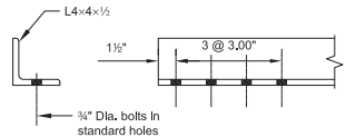
Verify, by both ASD and LRFD, the tensile strength of an L4×4×½, ASTM A36, with one line of (4) ¾-in.-diameter bolts in standard holed. The member carries a dead load of 20 kips and a live load of 60 kips in tension. Calculate at what length this tension member would cease to satisfy the recommended slenderness limit. Assume that connection limit states do not govern.
Solution
From AISC Manual Table 2-4, the material properties are as follows:
- L4×4×½
- ASTM A36
- Fy=36 ksi
- Fu=58 ksi
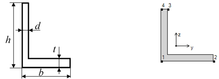
From AISC Manual Table 1-7, the geometric properties are as follows:
- L4×4×½
- Ag =3.75 in.2
- rz =0.776 in.
- γ‾ = 1.18in = χ‾
From Chapter 2 of ASCE/SEI 7, the required tensile strength is:
Tensile Yielding
From AISC Specification Section D2, the available tensile yielding strength is:
Tensile Rupture
Calculate U as the larger of the values from AISC Specification Section D3, Table D3.1 Case 2 and Case 8.
From AISC Specification Section D3, for open cross sections, U need not be less than the ration of the gross area of the connected element(s) to the member gross area, therefore, U = 0.500.
Case 2:
Case 8, with 4 or more fasteners per line in the direction of loading:
- U = 0.80
- Use U = 0.869.
Calculate A<n using AISC Specification Section B4.3.
Calculate Ae using AISC Specification Section D3.
From AISC Specification Section D2, the available tensile rupture strength is:
The L4×4×½ available tensile strength is governed by the tensile yielding limit state.
Example from AISC Design Examples
Material summary
Properties Summary
| Geometry Property | Value |
|---|---|
| Height | 4.00 |
| Width | 4.00 |
| h | 4.00 |
| b | 4.00 |
| d | 0.50 |
| t | 0.50 |
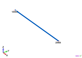
FEM Loads and Constraints
1..Dead load 20 kips
2..Live load 60 kips
1.Constraint
Check 1..ANSI / AISC LRFD 360-10
Axial Check
All (LS1, 17 Property Shape(s))
From Chapter 2 of ASCE/SEI 7, the required tensile strength is:
From AISC Specification Section D2, the available tensile yielding strength is:
From AISC Specification Section D2, the available tensile rupture strength is:
The L4×4×½ available tensile strength is governed by the tensile yielding limit state.
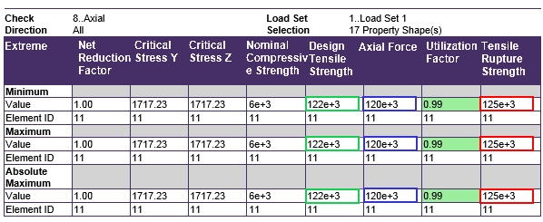
Comparing results of calculation in SDC Verifier and in Example D.2 we can see that values completely match.
- The required tensile strength is 120 kips.
- The available tensile yielding strength is 122 kips.
- The available tensile rupture strength 125 kips.
Full list of AISC 360-10 Examples


