ABS FPI Plate Buckling (2014)
An important aspect in the design of an offshore steel structure is the buckling and ultimate strength behavior of its fundamental structural components. To ensure high technical quality plate buckling check according to ABS 2014 Guide for building and Classing - Floating Production Installations, published July 2014.
Rules for building and classing floating production installations
To add ABS FPI Plate Buckling 2014 standard execute from the ribbon:
![]()
Press  to Set Standard Custom Settings
Maximum allowable strength utilization factor - critical buckling stress is multiplied on the utilization factor.
Thickness Factor - increases each plate thickness (e.g. 1.1 increase on 10%) and decreases stresses;
Pr - is a proportional linear elastic limit of the structures, which may be taken as 0.6 for steel;
Calculations are performed for each element with converted stresses (into plate direction) or Plate Average Stresses and using Plate dimensions.
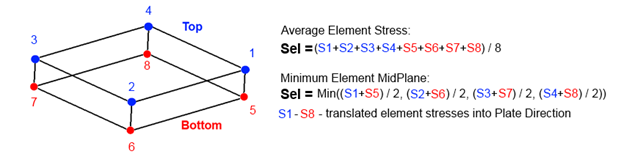
Stress on Element - which stress to check.
Average - average stress among element point of interests.
Min Midplane - minimum midplane stress (Stop + Sbottom / 2), without bending.
Use Absolute Shear for Plate Average - used only together with the plate average option and means that absolute shear is used for plate averaging:
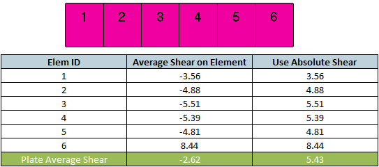
With Absolute Shear option, higher shear stress is used for checking, that makes verification more conservative.
Standard uses material data (Yield/Tensile) in calculations. Wizard checks if the values are defined for all materials.
Plate Buckling Check is calculated on Sections. With the help of Panel Finder tool it is possible to automatically recognize Section and Plates with their dimensions.
By default, all sections are included in the selection but can be changed by pressing  . If sections were not recognized, press
  to run Panel Finder tool.
Check is passed if Ultimate Strength Limit ≤1 and Buckling State Limit ≤1.
Plate Buckling Results
Calculation approach
For individual loads and loads sets, plate buckling is calculating based on formulas using stresses from the load. For Load Group plate buckling is calculated as an envelope. Load Group items are calculated using formulas and then min/max/abs is found. Load Group contains the worst values for each parameter and gives a possibility to check the highest Ultimate Strength and Buckling State Limits for all items at once.
Ultimate Strength Limit and Buckling State Limit depend on plate results (stresses) and the plate dimensions (length, width, and thickness).
Plate buckling check includes various options for stresses to be checked:
- Element Stress: MidPlane (no bending) or Average;
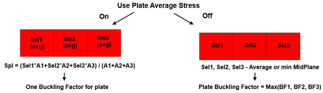
- Use Plate Average Stress - stress is averaged on the plate using elements area. The calculation is performed on every element but with averaged plate stresses.
- Use Absolute Shear for plate average (Conservative);
Note: for x and y directions only compression (negative) stresses are used in calculations. Positive stress is ignored and set to 0. For shear (xy) direction positive and negative stresses are used.
Stress Conversion
Plate Buckling check requires to verify element stresses (Sx, Sy and Txy) to be translated into the plate X, Y, XY directions.
Conversion of the stresses is done automatically in Plate Buckling check. For the element average option - the nodal element stresses at top and bottom are averaged (which is equivalent to using midplane centroid stress) and translated into plate directions. For Min Midplane option - the midplane stresses are translated into the plate directions and then the minimum values are taken.
SDC Verifier makes an assumption that plate elements are calculated without any output transformation and default values are used:
- For triangle elements x stress is oriented along the first edge (node1 -> node2 define 1 edge).
- For quad elements x stress is oriented along Diagonal Bisector:
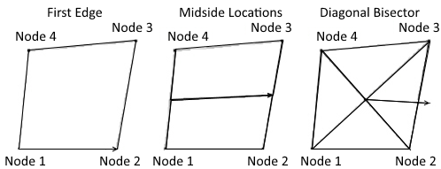
Execute in Femap main menu: - - and press . Check if orientation is set to the default values.
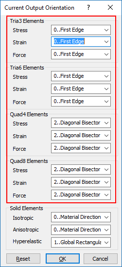
Plate Dimensions and Thickness
Results depend on the plate dimensions and direction. It is important to understand how the Panel Finder performs recognition. Length is considered to be the longest edge of the plate and width the longest perpendicular to the longest edge:
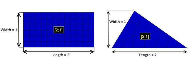
Plate dimentions can be calculated using CSR method - calculate equivalent rectangular plate dimensions described in Common Structural Rules (1 Jan 2018) Part 1, Chapter 8, Section 4 (2.3)
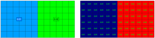
Calculations are performed on every element and thickness is taken directly from each element. It is possible to set thickness manually, in this case, element thickness will be ignored and user-defined thickness will be used.
Example: A plate with 2 properties 0.01 and 0.02 thicknesses. Left picture displays the property labels with property thicknesses and the right one presents plate buckling plot of thickness parameter:
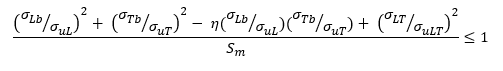
Buckling State Limit
The buckling state limit for the plate panels between stiffeners is defined by the following equation:
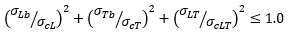

Where
σLb - total compressive stress in the longitudinal direction for the plate.
σTb - total compressive stress in the transverse/vertical direction.
σLT - total in-plane shear stress.
σcL, σcT, σcLT - critical buckling stresses corresponding to uniaxial compression in the longitudinal, transverse/vertical directions and edge shear.
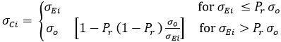 - critical buckling stress for uniaxial compression in the longitudinal/transverse direction and edge shear.
Pr = 0.6 for steel, proportional linear elastic limit of the structures.
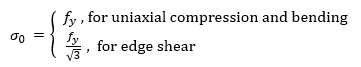
fy - Yield Stress.
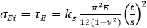
t - plate (element) thickness, s - plate width, v - poison ratio = 0.3.
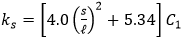
Buckling coefficient ks is calculated:
ks = 4.0*C1 - for longitudinal direction;
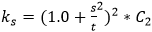 - for transverse direction
 - for shear direction.
Where s / l - plate width to the length ratio.
The coefficient C1 is equal to:
- 1.1 for plate panels between angles or tee stiffeners;
- 1.0 for plate panels between flat bars or bulb plates;
- 1.0 for plate elements, web plate of stiffeners and local plate of corrugated panels.
C2 can be defined:
- 1.2 for plate panels between angles or tee stiffeners;
- 1.1 for plate panels between flat bars or bulb plates;
- 1.0 for plate elements and web plates.
Ultimate Strength
The ultimate strength limit for plate panels between stiffeners is defined by the following equations:
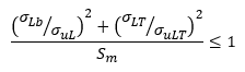
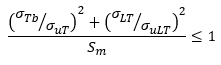
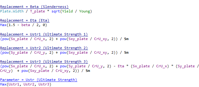
Sm = strength reduction factor. Subsection 5A-3-3/7.3.1
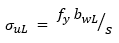 - ultimate strength with respect to uniaxial stress in the longitudinal direction (not less than critical x buckling stress).
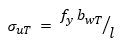 - ultimate strength with respect to uniaxial stress in the transverse direction (not less than critical y buckling stress).
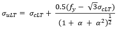 - ultimate strength with respect to edge shear (not less than critical shear buckling stress).
 - plate length to width ratio.
bwL, bwT - effective width in longitudinal and transverse directions respectively.
 - Yield Stress.