Standard
Standard – is a set of characteristics and checks to perform verification according to a design code.
The following standards are implemented:
- ABS OS Plate Buckling (2004)
- ABS FPI Plate Buckling (2014)
- ABS OS Plate Buckling (2022)
- ABS FPI Plate Buckling (2024)
- AISC ASD 1989 Members (9th, 1989)
- AISC 360-10 Members (14th, 2010)
- AISC 360-22 Members (2022)
- AISC 360-10 Bolts (14th, 2010)
- API RP 2A-LRFD (1st, 1993)
- API RP 2A-WSD (21st, 2007)
- AIJ (2005 Edition, 2017)
- AS 3990 (1993)
- AS 4100 (2020)
- ASME VIII (Div2, 2010)
- ASME B31.8 (2018)
- BV NR615 Plate Buckling (2023)
- DIN 15018 (1984)
- DNV-RP-C203 Fatigue(2016)
- DNV CN30 Plate Buckling (1995)
- DNV RP-C201 Plate/Stiffener Buckling (2010)
- DNV OS-C101-LRFD Weld Strength (2011)
- DNV OS-C201-WSD Weld Strength (2011)
- DVS 1608 (2010) and 1612 (2014)
- EN 13001 Fatigue (2018)
- EN 13001 Weld Strength (2018)
- Eurocode3 Members (EN1993-1-1, 2005)
- Eurocode3 Welds 1D (EN1993-1-8, 2005)
- Eurocode3 Weld Strength (EN1993-1-8, 2005)
- Eurocode 3 Fatigue (EN1993-1-9, 2005)
- Eurocode3 Bolts (EN 1993-1-8, 2005)
- Eurocode3 Fire Design (EN1993-1-2, 2005)
- Eurocode3 Plate Buckling (EN 1993-1-5, 2006)
- Eurocode3 Connections (EN 1993-1-8, 2005)
- FEM 1.001 (3rd, 1998)
- FKM (5th, 2003)
- FKM (6th, 2012)
- ISO 19902 (1st, 2007)
- ISO 19902 (2nd, 2020)
- Norsok N004 (rev.3, 2013)
- VDI 2230 (Part 1, 2015)
- Custom Standard
- Deflection / Serviceability check
- Comparison Standard
Plate Buckling Results
Criteria Plot
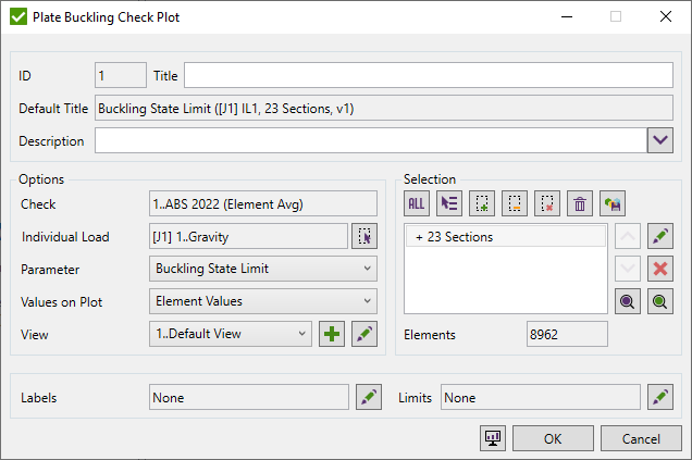
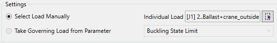
Select Load, Parameter, Values to plot, View,and Sections to Plot.
The parameter is set by default to the last one - Buckling State Limit.
Load should be selected using Single Load Selector;
Values to Plot - can be used for plotting: element values, min plate, max plate and average plate (last 3 variants use one value for the full plate).
View - defines the location of a model and displays options.
Labels - include labels with extreme values over buckling plates.
Limits - filter elements/node selection based on the result criteria.
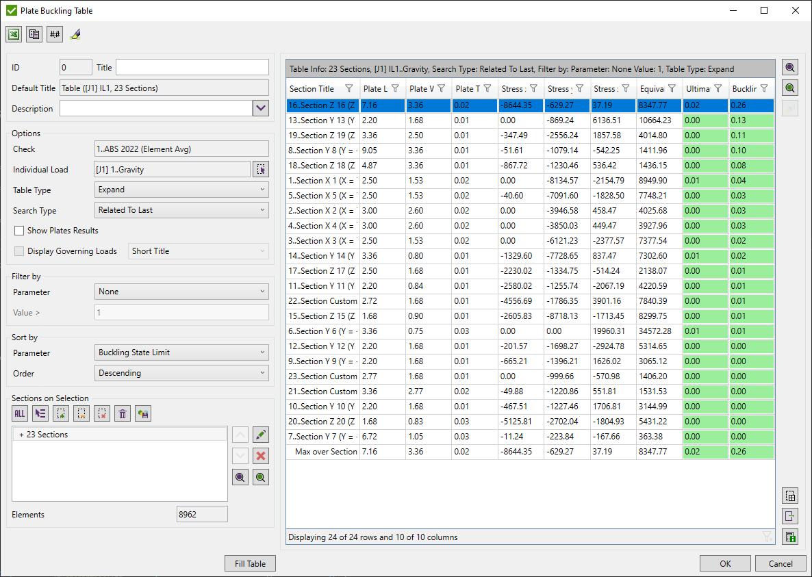
Table (Expand/Extreme)
Expand Table display results for each selected section and its plates. Extreme table show only min/max and absolute maximum results among selected sections.
Common commands are described in the Common Options chapter
Load should be selected using Single Load Selector;
Table type - expand - results over sections/plates, extreme - min/max/absolute maximum overall sections only.
Search type - display results for each section/plate taking the worst result from all elements of the section/plate
- Min, Max, Absolute Max - the worst result is taken from all parameters of the check.
- Related to Last Parameter - the worst result will be taken only from the last parameter of the check. The rest results will be taken only from that element which contains the worst result by the selected Search Type.
Show Plates Results - displays results over the plates for each section if turned on. Otherwise, displays the results over sections only. Available for an expand table only.
Governing Loads - display what load case cause the highest buckling state limit (short or full title).
Filter and sort results using Filter / Sort By control.
Select sections using Selector Control. It is enough to pick one element from section to include it.
 - highlight selected sections/plates;
 - display only selected sections/plates;
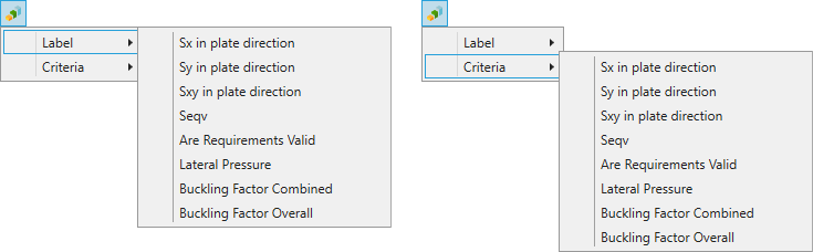
 - press to display selected section/plates with result as labels:
- Label - display worst results with labels for each selected plate;
- Criteria - display results for each element;
 - select element from the model and highlight section/plate which contains it in the table;
 - export selected plates (using Export Menu);
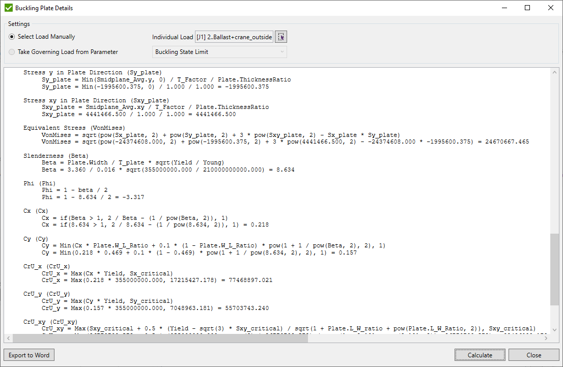
 - display calculation details (stress calculations, all formulas) for single selected plate.
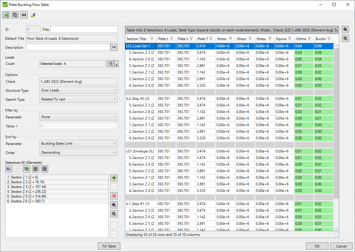
Flow table (over loads)
A Flow table displays results for multiple selections/loads.
Common commands are described in the Common Options chapter
Select Loads using Multiple Load Selector.
Define Selections using Selection List.
Filter and sort results using Filter / Sort By control.
Structure Type - display all load results under each selection or all selections under each load;
Search type - display the worst result for each selection/load:
- Min, Max, Absolute Max - the worst result is taken from all parameters of the check.
- Related to Last Parameter - the worst result will be taken only from the last parameter of the check. The rest results will be taken only from that element which contains the worst result by the selected Search Type.
Weld Strength Settings
Select Welds

By default all welds that match the following criteria are included into the selection but can be changed by pressing  .
.
Weld is included in calculations if it is:
1. Straight with the tolerance of 3 degrees;
2. Double-symmetric - weld is formed by 2 planes that are perpendicular to each other with the tolerance of 5 degrees;
Preview weld elements that are not verified press  .
.
Preview selected weld elements by pressing  .
.
If welds are not recognized press  to run the Weld Finder tool.
Note: In results only welded parts are calculated. The rest of the parts will not contain results.
Geometrical Check
If Include geometrical check option is ON, an extra check with minimum/maximum weld length and throat thickness will be added to the standard:

Press  to set formulas for the check:
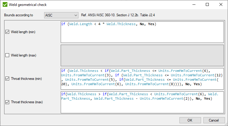
It is possible to select 3 predefined types of bounds and custom:
- Eurocode 3 - EN 1993-1-8, chapter 4.5.1 (2) and 4.5.2 (2);
- AISC - ANSI/AISC 360-10, Table J2.4;
- AWS - AWS D1.1:2010, chapters 2.4.2.1, 2.4.2.3, 2.5.4, table 5.8;
- Custom - define all bounds manually. Tip for formulas is shown:

Remove 'Tip:' and set an 'input value in model units' to make the formula correct.
Result check will contain all included parameters and overall parameter that defines if all bounds pass:
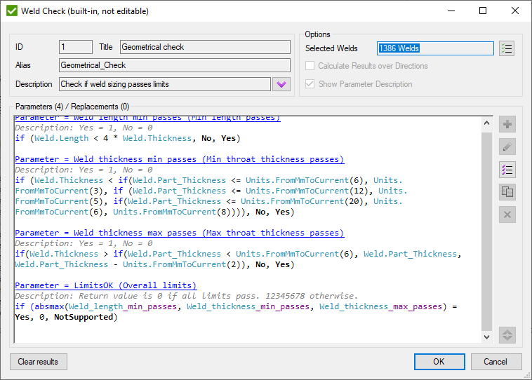
LimitsOK parameter returns 0 if all limits are OK and 12345678 otherwise.
Yield/Tensile Option

Use Yield/Tensile from - option which defines the Yield Stress/Tensile Strength to use in calculations (from Element/Material or from Weld Finder). By default minimum value of Yield/Tensile Strength is calculated using all weld elements and can be redefined in Weld Finder.
Calculation Method

Calculation Method defines the way of results calculations/presentation - full weld part or elemental-nodal. They are described in Weld Force Summation Tool.
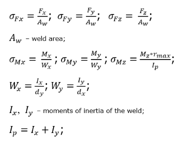
Weld Stresses
Stresses due to forces are calculated using the weld area, and due to moments using the inertia of the weld.
Note: Forces/Moments for both methods are retrieved from Weld Force Summation Tool. Weld length (used in calculations of area/inertia) and coordinate system are based on the selected method:
- Summarize per weld part - one coordinate system and weld length for full weld, taken from Weld Finder Tool;
- Summarize (Elemental-Nodal) - different coordinate systems and weld lengths for each node. Values are calculated by Weld Force Summation Tool.
Note: Weld inertia is calculated assuming that an effective weld section is horizontal and the weld is double-symmetric.
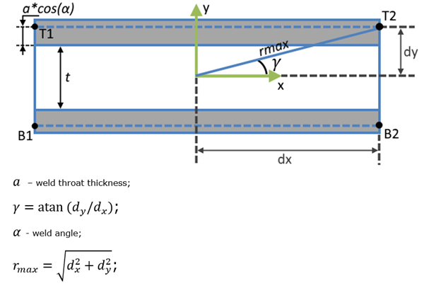
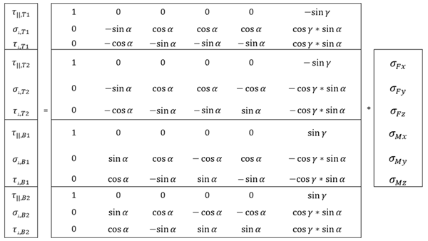
Stresses are rotated into weld X, Y, and XY directions and translated to points on the weld face at each end of the weld (T1, T2, B1 and B2).
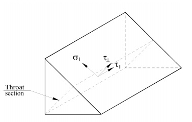
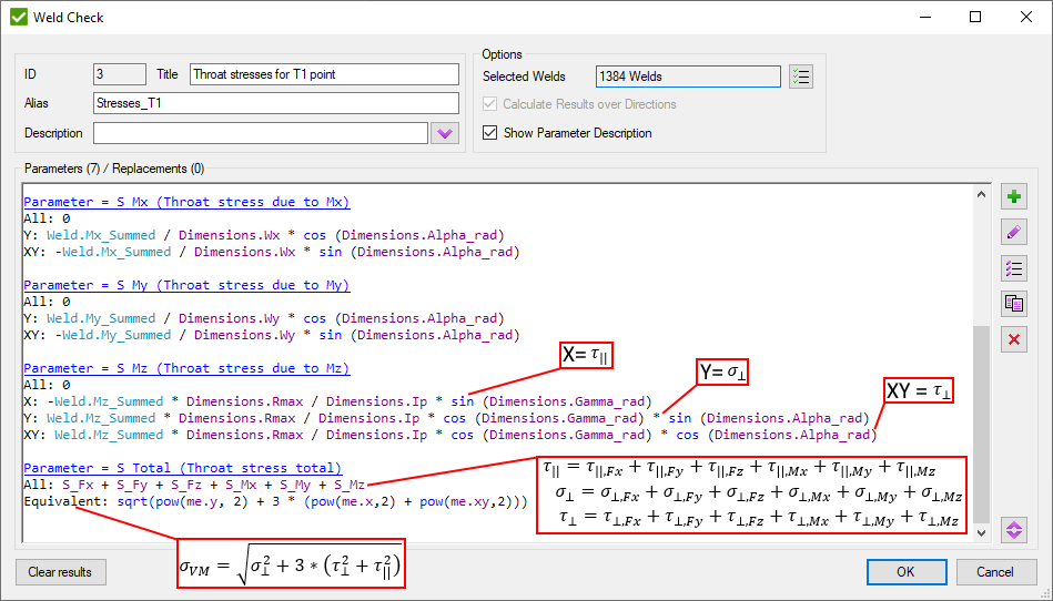
T|| - shear design stress (in plane of the throat) parallel to the axis of the weld (equal to X direction in the check);
σ⊥ - normal design stress perpendicular to the throat (equal to Y direction of the check);
T⊥ - shear design stress (in plane of the throat) perpendicular to the axis of the weld (equal to XY direction of the check);
Following matrix of rotation is used:
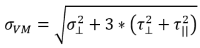 - Von Mises stress at a certain point. Stress is used in calculations of weld capacity in design standards;
Example of the check for point T1:
Joint Check
Common Joint Check Settings
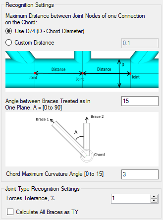
Maximum distance from joint nodes of one connection on the chord - include joints that are formed by multiple nodes:
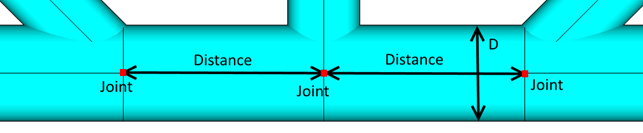
It is possible to set Custom distance or use the distance that equals D/4 where D - chord diameter so that each connection has its own distance to check.
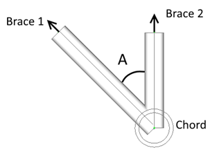
Angle between braces treated as in one plane - defines the allowable angle between braces of one connection that are located in different planes:
Chord maximum curvature angle - Not always chord elements form the straight line. To include an inclination in chord default angle = 3 degree is used.
Force Tolerance - type of brace depends on the axial forces of members of the connection. This option defines allowable tolerance for the total force that is used in calculations of the brace type.
Calculate all braces as TY - Joint type is based on loading. This option will ignore loading and set all joint types for a brace to TY.
Criteria Plot
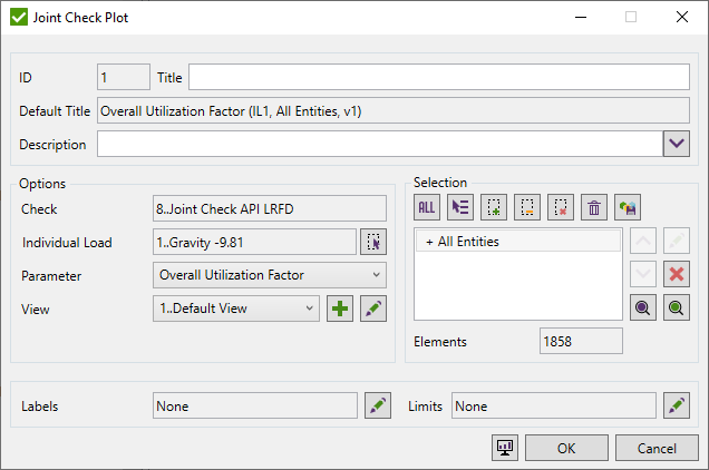
Select Load, Parameter, View, and define Selection to Plot.
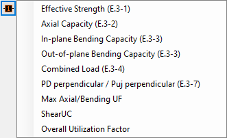
The parameter is set by default to the Overall Utilization Factor.
Load should be selected using Single Load Selector;
Define Selection using Selector Control. Connections where at least one element exist in selection will be displayed on the plot.
Note: The results are displayed only for braces.
View - defines the location of a model and displays options.
Labels - include labels with extreme values over braces.
Limits - filter selection based on the result criteria.
Expand Table
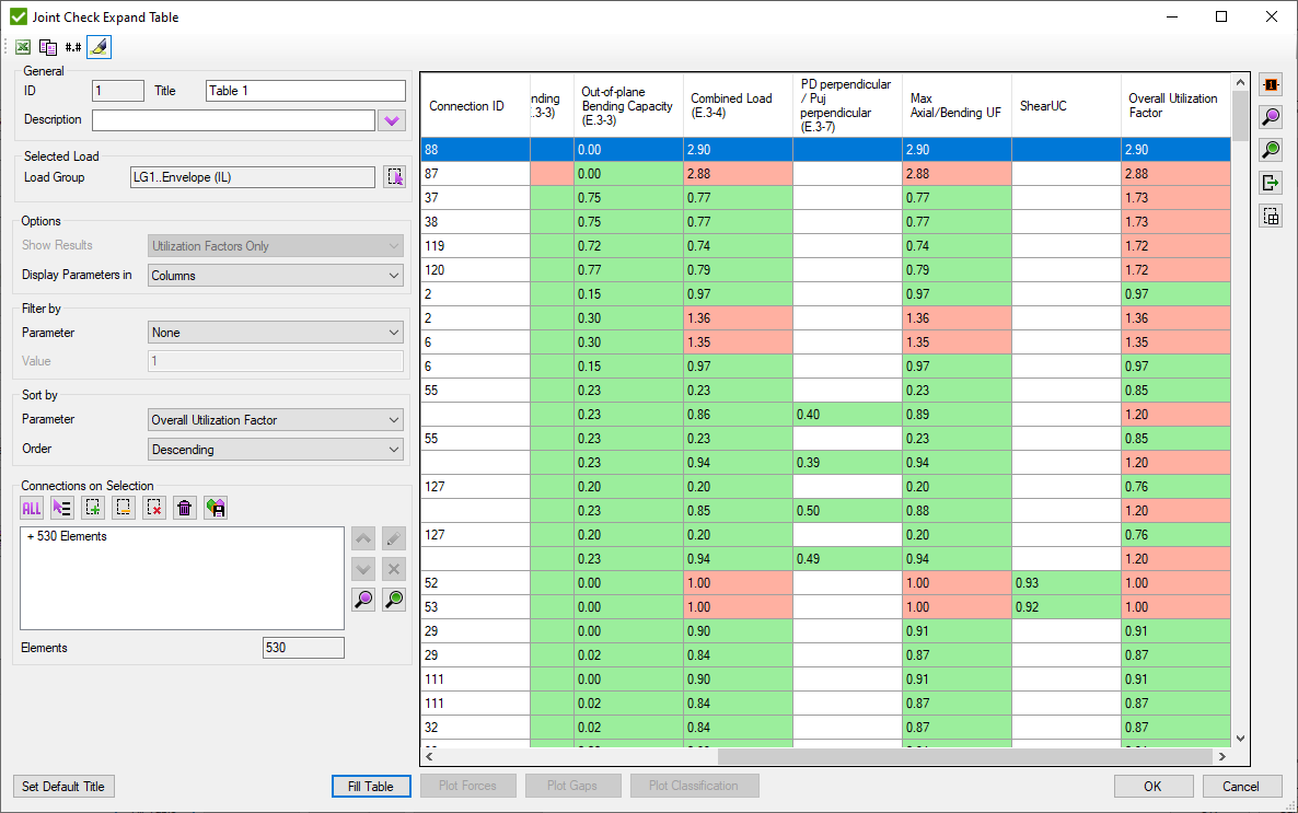
Common table commands (e.g. export to Excel) are described in Common Options chapter.
Show results:
Utilization factors only - Effective strength, joint axial and bending capacities, combined load and overlapping calculations;
Intermediate - axial and bending stresses of the chord and braces + utilization factors;
All - Intermediate results + calculation factors (Qf, Qu)
Display Parameters in:
Rows - display parameters in rows and connections info in column headers.
Columns - display parameters in column headers and connections information in rows.
Select Load using Load Selector.
Define selection using Selector Control. Connections where at least one element exist in selection will be displayed in the table.
Filter and sort results using Filter / Sort By control.
-
open the list of available parameters in the table to plot. Labels of results will be shown for each selected brace:
 - export selected welds in the list using
Export Selected Items Menu
- export selected welds in the list using
Export Selected Items Menu
- select element from the model and
highlight connections that contain selected element in the table;
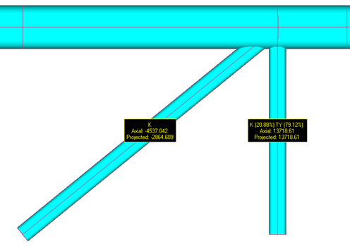
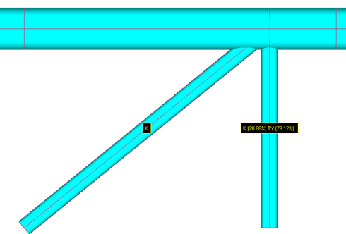
 - Plot Axial force and Projected force of all braces of the selected connections:
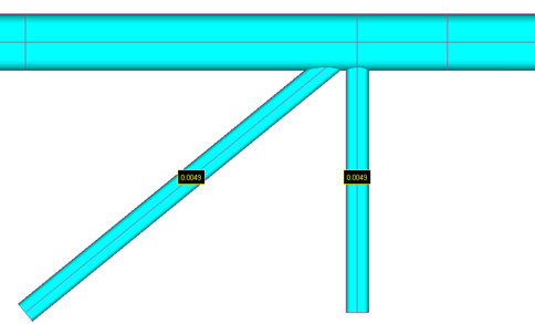
 - Plot gaps of all braces of the selected connections:
 - Plot braces types of the selected connections:
Flow Expand Table
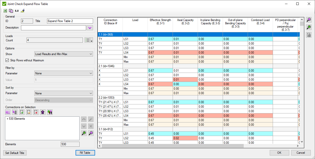
Common table commands (e.g. export to Excel) are described in Common Options chapter.
Show:
Load Results - display results for each selected load per brace.
Min/Max - display only minimum and maximum results among the loads for each brace.
Load Results and Min/Max - combines two previous options.
Skip rows without maximum - do not display loads that do not contain any extreme results among all parameters.
Select Load using Multiple Load Selector.
Define selection using Selector Control. Connections where at least one element exist in selection will be displayed in the table.
Filter and sort results using Filter / Sort By control.
- select element from the model and
highlight connections that contain selected element in the table;