Deflection / Serviceability check
For civil engineering and many other industries, it is important to ensure that a structure meets the functional requirements - the Serviceability limit state (SLS). It does not involve collapse or strength of a building but impairs it usefulness and stiffness.
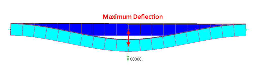
Deflection is the displacement within a structural member under the influence of loads, ignoring the displacements of the rest of the structure.
To add deflection check, first Custom Standard has to be created - execute from the the main menu. Then execute from the Checks context menu:
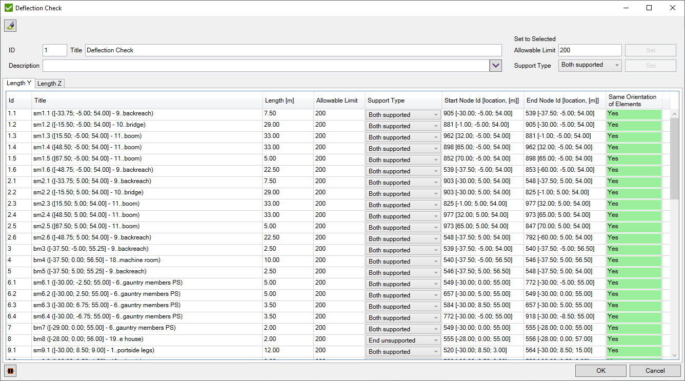
On the deflection form, the lists of beam members/sub-members in Y and Z direction are shown. It is possible to set the Allowable Limit, Support Type. By default allowable limit is set to 200 and support type is defined based on Joints recognized in the mode.
In general, the deflection limits are based on the beam member's lengths (span) which results in different allowable deflections in every point or node of the construction. For example, the serviceability limits suggested by the UK National Annex for the Eurocode 3 (BS EN 1993-1-1) for allowable vertical and horizontal deflections are shown below:
| Cantilevers | Length/180 |
| Beams carrying plaster of brittle finish | Span/360 |
| Other beams (except purlins and sheeting rails) | Span/200 |
| Purlins and sheeting rails | To suit the characteristics of particular cladding |
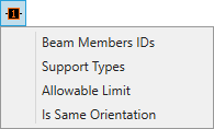
Values can be edited directly in the table for a single member or using the following control for few members:
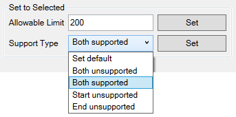
Set default - set type based on recognized joints. If both ends are unsupported the member cannot be calculated.
For each member in the table start/end node id, location and member's elements orientation check are shown:
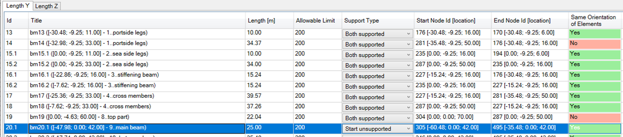
Deflection is calculated in the local element coordinate system and it is important that the orientation of all line elements were in the same direction.
To display label plot for selected members press  :
:
Support Type Plot:
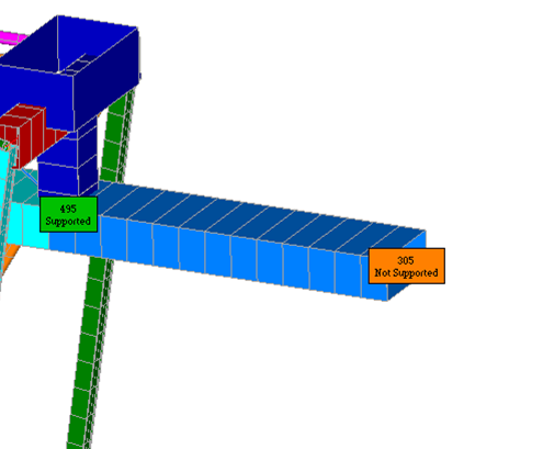
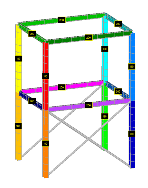
Allowable Limit Plot:
Table
Execute from the Deflection Check context menu:
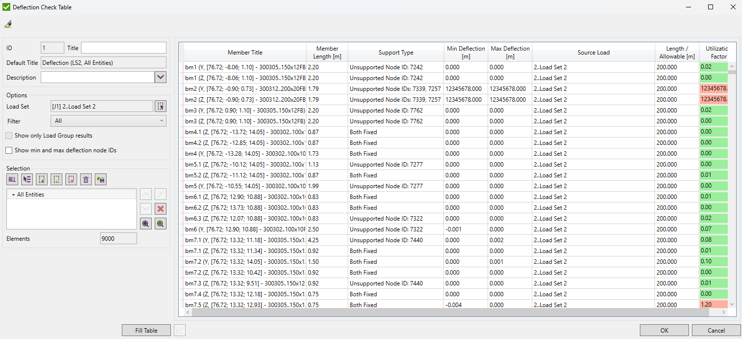
Select Load using Load Selector control.
By default members in Y and Z directions are shown. It is possible limit members by Filter (only Y direction, only Z, major axis, minor axis) or Selection (member will be displayed if all elements of members are in selection).
Show only envelop results - display only envelop results (not load group items results);
Show deflection location - display nodes ids for minimum and maximum deflections;
Press to display data.
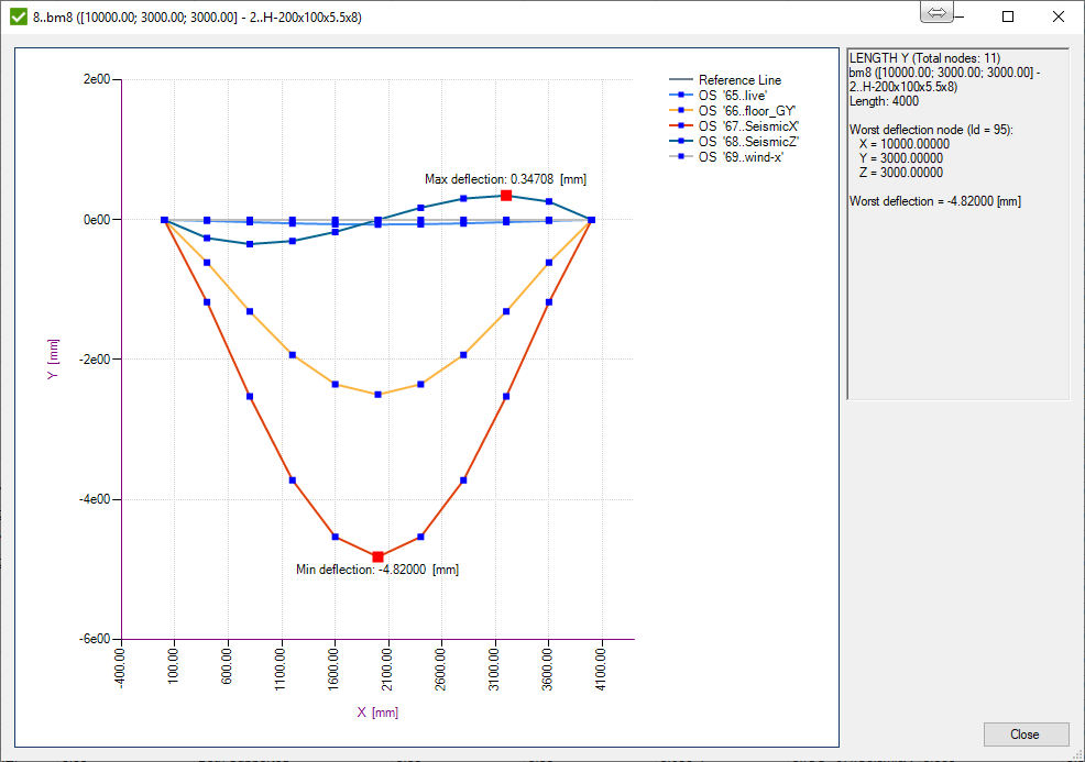
Select single member and press  to display the deflection graph (for Load Group if option Show only worst results is OFF, the deflection for all load group items will be shown, otherwise, only envelop graph):
Criteria Plot
Execute from the Deflection Check context menu:
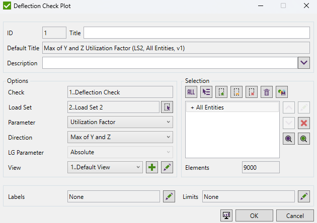
Select Parameter, Direction, View, LG Parameter (for Load Group only) and press  .
.
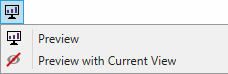
 display plot with all the settings;
 - display plot with current view settings (ignore view from plot options);
Use Labels to include labels with extreme values over recognition items (members), display min/max values.
Limits are described in Common Controls chapter.