API RP 2A-LRFD (1st, 1993)
API RP 2A-LRFD checks the structural strength and stability requirements for steel cylindrical elements. Sections D (Cylindrical Member Design) and E (Connections) are implemented.
This standard is applied to the cylindrical members with the Thickness ≥ 6mm, ratio D / t < 300 and Yield < 414 MPa.
To add the Standard execute from the ribbon:
![]()
Press  to Set Standard Custom Settings
Safety Factors are set to Standard default values. It is not necessary to change them.
According to the calculation procedure, Beam Length for Y and Z direction is required. Data from Beam Member Finder is used automatically.
If beam members are not recognized press  .
.
Standard uses material data (Yield/Tensile) in calculations. Wizard checks if the values are defined for all materials.
It is possible to use API 2A RP (1st, 1993) in combination with AISC 360-10 Members (14th, 2010) standard.
Set option Use AISC 360-10 for non-tubular shapes checked to use the standard for non-tubular elements.
Press  to define settings.
Note: If the AISC 360-10 is included - 3 standards will be created:
- API RP 2A-LRFD - circular tubes are calculated according to API LRFD;
- AISC 360-10 - all supported shapes are calculated according to AISC 360-10;
- AISC and API - combined standard where results for circular tubes are taken from API RP 2A-LRFD and results for other supported shapes - according to AISC 360-10.
Joint Check
Joint Check is a part of the API RP 2A-LRFD standard but is available for Custom Standard. To create a new Joint Check execute from the checks context menu of a respective standard.
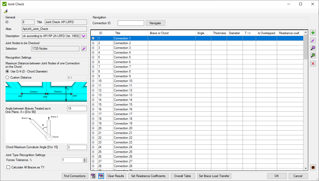
Press  to automatically highlight single Connection selected in the table.
Recognition Settings are described in Common Options chapter.
Set Connection ID and press to display connection in the table.
Joint check is based on the connections. Each connection is a set of elements near joint node (see Joints Finder). Connections consists of Chord and braces. Brace contains only 1 element with ID defined in brackets (#). Connection can contain braces from both sides of the chord. The information is displayed in the second brackets: U- upper braces; L- lower braces;
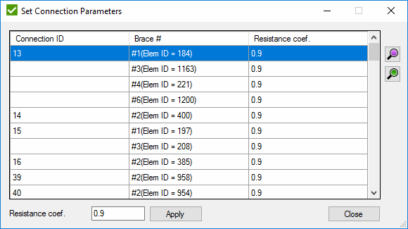
Press to find all connections of the model. A window with connections that are recommended to be checked manually will be displayed:
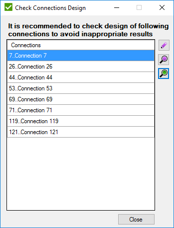
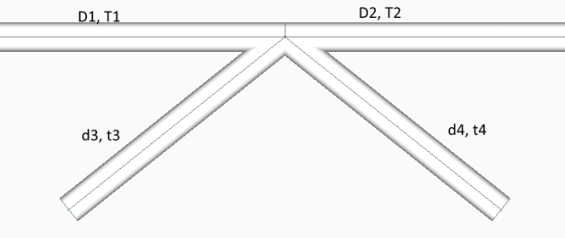
Connection has to be checked when:
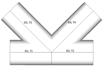
- D1 = D2 = d3 = d4, T1 = T2 = t3 = t4
- D1 = D2 = d4, T1 = T2 = t4, d3 > D1
- D1 = D2 = d3 = d4, T1 = T2 = t4, t3 > T1 according to the following image
 - Add a new connection manually:
 - edit the selected connection;
 - preview - highlight the selected connection;
 - preview only selected connection;
 - remove the selected connection;
 - plot all connections values in colors + Labels with IDs;
 - show an information about all connections;
 - hide an information about all connections.
![]() - clear all calculations for loads;
- clear all calculations for loads;
Edit Connection
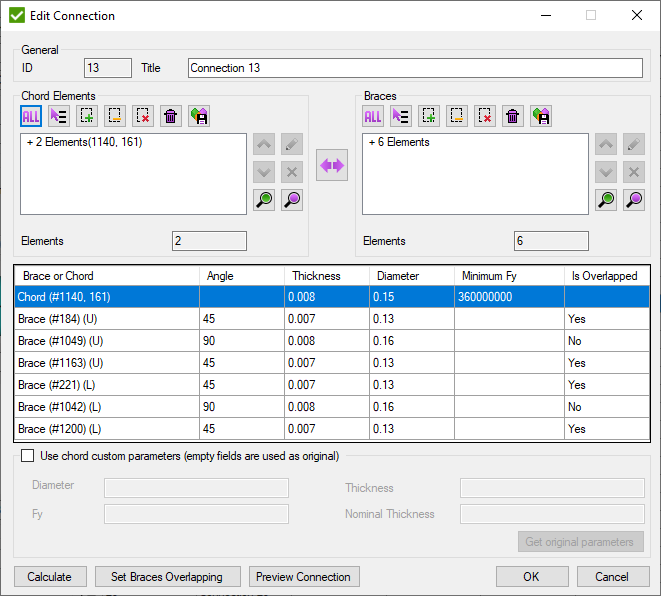
Pick Chord elements and braces (each brace consist of 1 element) and press to preview the connection properties.
 - swap chord and brace elements.
Press to highlight the connection on the model.
- open a window to set the overlapping brace. It is enabled only if one brace overlaps another one in the connection:
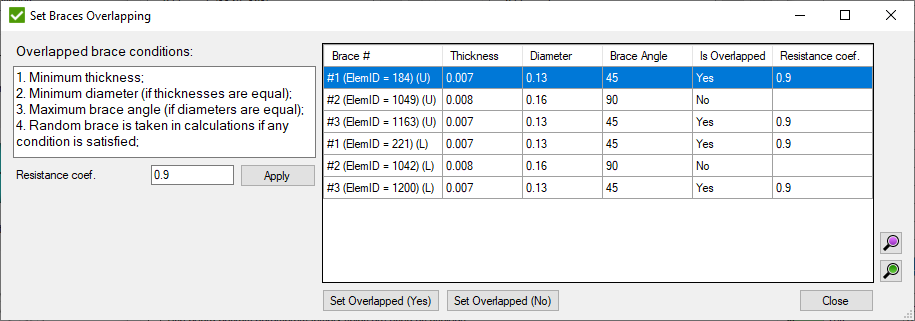
Resistance Coef. - AISC resistance factor for the weld (Φsh).
- set to the selected braces if they are overlapped.
 - set resistance coefficient for overlapped braces:
All overlapped braces are displayed in the list with the related connection ID.
Fill Resistance coef. and press to set the coefficient to all selected braces.
If no overlapped braces are found, a message will be displayed:
![]() - displays a window to set Load transfer (section E.3.4 in standard) for braces of connections which contain can:
- displays a window to set Load transfer (section E.3.4 in standard) for braces of connections which contain can:
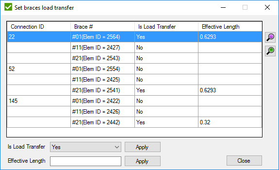
If load transfer is set to "No", formula (E.3.4-1a) will not be applied to the calculations, even if it matches the conditions.
It is possible to change the Effective Length manually. Set value to Effective Length field and press to set value to the selected braces.
Joint Check Results
- Criteria Plot
- Expand Table
- Flow Expand Table
 - a detailed table with all intermediate results:
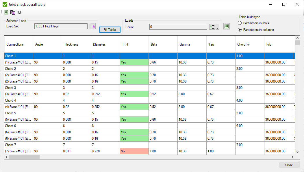
Select Load and press to display the results.
 - export multiple loads results to excel file;
Mathematical background
All calculations are performed in accordance to API RP 2A-LRFD - Offshore platform loading standard (Section E).
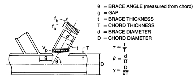
Geometric parameters that are used in calculations are obtained by the following equations:
The effective strength is defined as the buckling load for members loaded in either tension or compression, and as the yield load for members loaded primarily in tension:
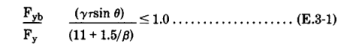
where
Fy = the yield strength of the cord member at the joint (or 2/3 of the tensile strength if less), in stress units
Fyb = the yield strength of the brace member in stress units
Note: When a chord is formed by different properties parameters for such connections are updated (see Particular cases).
Brace Types. According to standard, joint types are defined by the following rules:
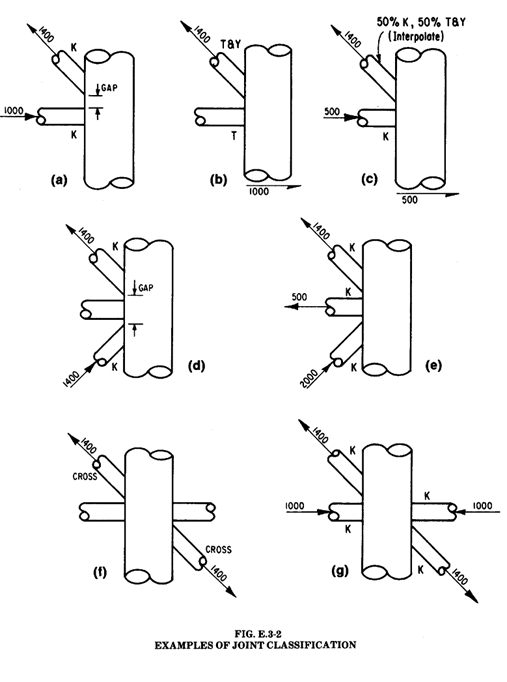
The Joint type is based on the type of loading. By checking if forces of the connection are balanced, joint types are classified into K, TY, and X (Cross).
K - tension and compression loads are balanced.
TY - tension or compression load goes as a shear force in a chord.
X (Cross) - Connection has to contain braces from both sides to check on cross joint. If balanced forces of all braces of one side and balanced forces of all braces of other side are equal then all braces are classified as X (Cross).
Interpolation - the order of joint type recognition is following: K -> X (Cross) -> TY. Each brace can have all 3 types of joint type taken as the percentage of axial load of brace to the summation of all braces loads.
Note: If the brace has zero force, the joint type for such brace is set to TY.
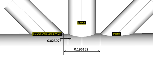
Gap calculations. Gap is a minimum distance between two differently loaded braces (tension and compression) measured on a shell of the chord. It is possible that brace can have two or more gaps to considerate. Each gap percentage depends on the percentage of the taken load:
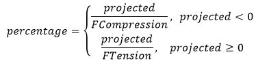
Projected - brace axial force that is perpendicular to the chord;
Ftension - sum of all positive projected axial forces;
Fcompression - sum of all negative projected forces.
Example of gaps:
Strength check. Joint capacity shall satisfy the following:
PD < φPuj........(E.3-2)
MD < φMuj........(E.3-3)
where
PD = the factored axial load in the brace member, in force units
Puj = the ultimate joint axial capacity, in force units
MD = the factored bending moment capacity, in moment units
Muj = the ultimate joint bending moment capacity, in moment units
Φj = resistance factor tubular joints taken from the table below
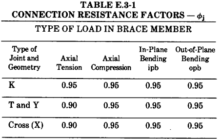
For braces which carry part of their load as K-Joints and part as T & Y or Cross joints, interpolate Φj is based on the portion of e ach in total:
Φj Total = (K percentage)* Φj + (T&Y percentage)* Φj + (Cross persentage)+ Φj
For combined axial loads and bending moments in the brace, Equation E.3.2 should be satisfied along with the following interaction equation:
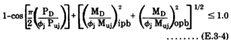
where
Ipb - in-plane bending
Opb - out-of-plane bending
The ultimate capacities are defined as follows:

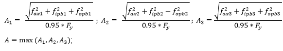
Calculations of A parameter are the following:

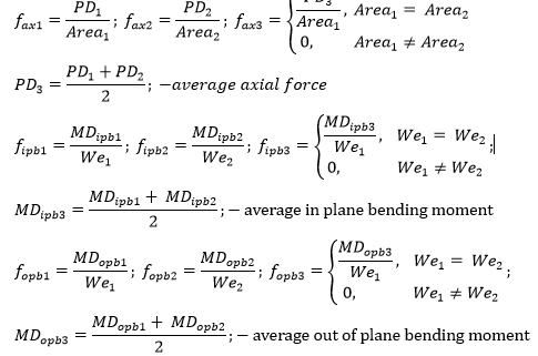
Axial and bending stresses.
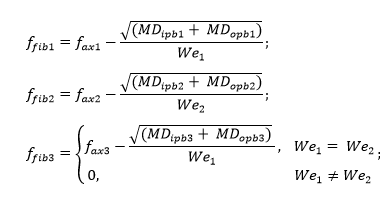
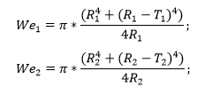
Extreme Fiber Stresses.
Extreme Fiber stress is a difference between axial and bending stresses:
Elastic modulus.
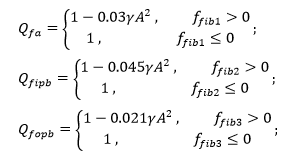
Qf is calculated for axial, in plane bending and out-of-plane bending parameters separately:
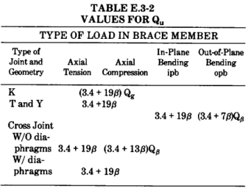
Quis the ultimate strength factor which varies with the joint and load type:
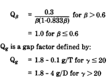
Note: In no case Qg should be taken less than 1.
For braces which carry a part of their load as K-Joints and part as T&Y or Cross joints, interpolate Qu is based on the portion of each in total:
Qu total = (K percentage) * Qu + (T&Y percentage) * Qu + (Cross percentage) * Qu
Load Transfer
| Puj = P(1) + (L / 2.5D) * (P(2)-P(1)), | for L < 2.5D (E.3.4-1a) |
| Puj = P(2), | for L > 2.5D (E.3.4-1b) |
where:
P(1) = Puj from equation E.3.5 using nominal element geometric parameters (diameter, thickness, area, Fy);
P(2) = Puj from equation E.3.5 using can element geometric parameters (diameter, thickness, area, Fy);
Note: Load transfer calculations are applied when:
- Chord has increased thickness Tc;
- Effective length L matches the conditions like shown on the picture below;
- Brace chord diameters ratio (d/D) is less than 0.9, where D - diameter of a can element;
Note: Compression members are required to be checked on the load transfer, however it is possible to set the load transfer manually;
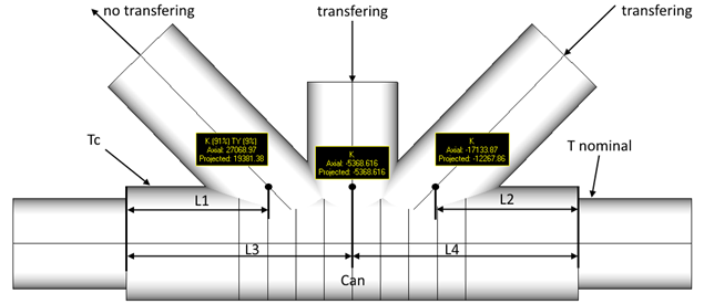
Effective length L is calculated for each brace separately. It is a minimum distance from the end of can till the point of intersection of chord and brace multiplied on 2.
Tc ≥ T nominal;
L1, L2 ≤ 1.25D. If L1 and L2 exceed 1.25D distance, can will not be recognized;
D - can diameter;
L = 2 * L1 - effective length for the left brace;
L = 2 * L3 = 2 * L4 - effective length for the middle brace;
L = 2 * L2 - effective length for the right brace.
Overlapping joints
The factored axial Force component perpendicular to the chord PD⊥ should satisfy the following equation:

where
vw = ΦshFy
Φsh = the AISC resistance factor for the weld
tw = the lesser of the weld throat thickness or the thickness, t, of the thinner brace
l1 = circumference for that portion of the brace which contacts the chord (actual length)
l = circumference of the brace contact with the chord neglecting the presence of overlap
l2 = the projected chord length (one side) of the overlapping weld, measured perpendicular to the cord
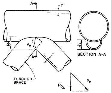
Note: Brace contacts chord under the angle creating elliptical intersection. SDC Verifier treats that kind of intersection as circular intersection so that l and l1 parameters are measured as circular circumferences:
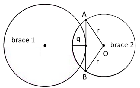
d=2*r;
l=π*d;
q'=q*sin(θ2);
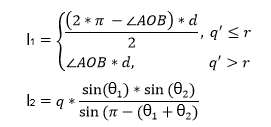
∠AOB - angle in radians;
θ1 - inclination of brace 1 to the chord;
θ2 - inclination of brace 2 to the chord;
Resistance coefficient φsh depends on the strength of welding and is used in calculations of overlapping (Section E.3.2 API 2A RP LRFD). A table is taken from Load and resistance factor design specification for structural steel buildings December, 27 1999. The default value in SDC is set to 0.9.
The design strength of welds shall be the lower value of (a)φFBMABM and (b)φFwAw, when applicable. The values of φ,FBM, and Fw and limitations thereon are given in Table J2.5,
where
| FBM | - nominal strength of the base material, ksi (MPa) |
| Fw | - nominal strength of the weld electrode, ksi (MPa) |
| ABM | - cross-sectional area of the base material, in.2(mm2) |
| Aw | - effective cross-sectional area of the weld, in.2 (mm2) |
| φ | - resistance factor |
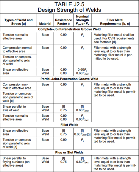
| [a] | For definition of the effective areas, see Section J2. |
| [b] | For matching filler metal, see Table 3.1, AWS D1.1. |
| [c] | Filler metal is one strength level stronger than matching filler metal is permitted |
| [d] | For T and corner joints with the backing bar left in place during service, filler metal with a classification requiring a minimum Charpy V-notch (CVN) toughness of 20 ft-lbs. (27 J) @ +40° shall be used. If filler metal without the required toughness is used and the backing bar is left in place, the joint shall be sized using the resistance factor and nominal strength for a partial-joint-penetration weld. |
| [e] | Fillet welds and partial-joint-penetration groove welds joining component elements of built-up members, such as flange-to-web connections, are not required to be designed with regard to the tensile or compressive stress in these elements parallel to the axis of the welds. |
| [f] | The design of connected material is governed by Sections J4 and J5. |
| [g] | For alternative design strength, see Appendix J2.4 |
Particular cases
Sometimes models cannot represent the real situations. For such cases calculations are updated to get the worst possible result according to the parameters:
Case 1:
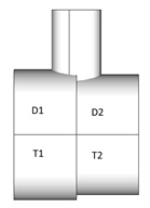
When Chord is formed by elements with different properties around the joint node and D1<>D2, D = min(D1, D2); T = min(T1, T2) are considered for calculations.
Case 2:
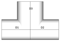
D1=D2, D1<D3. For such case D3 is recognized as chord as it has bigger diameter. Naturally pipe of bigger diameter cannot be welded to smaller. Such connections are recommended to be checked.
Case 3:
a)
D1 = D2 = D3 = D4;
T1 = T2 = T3; T4 >T4;
When all diameters of the connection are equal, thicknesses are compared. Element with thickness = T4 is recognized as chord.
b) In case when:
D1 = D2 = D3 = D4;
T1 = T2 = T3 = T4;
When all elements of the connection are of the same dimensions, chord is recognized as the pair of elements that form straight line. If any pair that matches the conditions is found, random element will be recognized as chord.