AISC 360-10 Bolts (14th, 2010)
AISC 360-10 Bolts (14th, 2010) - an American national standard "Specification for Structural Steel Buildings" released in June 22, 2010. This standard implements chapter J3. Bolts and Threaded parts.
To add AISC 360-10 Bolts standard execute from the ribbon:
![]()
Press  to Set Standard Custom Settings
Nominal Bolt Diameter is taken as the radius of the line (beam) element by default. User can override bolt diameter using characteristic (keep 0 to use from the model).
Characteristic Bolt Area Include Thread influence on Nominal Shear Strength (Table J3.2). Set No if property excludes thread, Yes - when includes:
|
Threaded parts meeting the requirements
of Section A3.4, |
0.75 Fu | 0.450 Fu |
|
Threaded parts meeting the requirements of Section A3.4, |
0.75 Fu | 0.450 Fu |
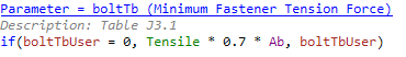
The Minimum fastener tension force by default is taken as 70% of the minimum tensile strength of bolts (Table J3.1 and J3.1M). It is possible to override it in Minimum fastener tension characteristic:
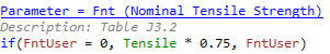
Nominal Tensile Strength by default is taken 75% of the minimum tensile strength of bolts (Table J3.2). It is possible to override the value in Nominal Tensile Strength characteristic:
Nominal Shear Strength by default is taken 56.3% or 45% of the minimum tensile strength of bolts (Table J3.2). It is possible to override the value in Nominal Shear Strength characteristic:

Slip Critical Connections
Slip-critical connections (chapter J3.8) shall be designed to prevent slip and for the limit states of bearing-type connections. When slip-critical bolts pass through fillers, all surfaces subject to slip shall be prepared to achieve design slip resistance.
Safety factors depend on Hole Type (chapter J3.2):
| (a) For standard size and short-slotted holes perpendicular to the direction of the load | |
| φ=1.00 (LRFD) | Ω=1.50 (ASD) |
| (b) For oversized and short-slotted holes parallel to the direction of the load | |
| φ=0.85 (LRFD) | Ω=1.76 (ASD) |
| (c) For long-slotted holes | |
| φ=0.70 (LRFD) | Ω=2.14(ASD) |
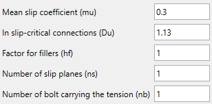
The following parameters should be set to perform slip critical check (set mean slip coefficient to 0 to skip the check):
Bearing Strength at Bolt Holes
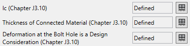
For strength bearing check it is required to input lc (clear distance between the edge of the hole and edge of the material), the thickness of connected material and deformation at the hole is a design consideration.
| (a) For a bolt in a connection with standard, oversized and short-slotted holes, independent of the direction of loading, or a long-slotted hole with the slot parallel to the direction of the bearing force | |
| (i) When deformation at the bolt hole at service load is a design consideration | |
| Rn 1.2lctFu ≤ 2.4dtFu | (J3-6a) |
| (ii) When deformation at the bolt hole at service load is not a design consideration) | |
| Rn 1.5lctFu ≤ 3.0dtFu | (J3-6b) |
| (b) For a bolt in a connection with long-slotted holes with the slot perpendicular to the direction of the force | |
| Rn=1.0lctFu ≤ 2.0dtFu | (J3-6c) |
To skip strength bearing check set lc characteristic to 0.
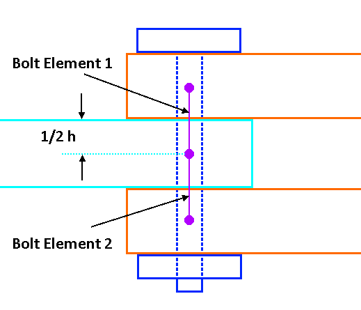
For the bearing, strength check the shear force of the element of the bolt is used. For planes with a continuous bolt only half of the plate thickness is available for the shear on that side: