EN 13001 Fatigue (2018)
EN 13001 Fatigue (2018) – a crane standard EN 13001-3-1+A2 Limits States and proof competence of steel structure.
To add EN 13001 Fatigue (2018) Standard execute from the ribbon:
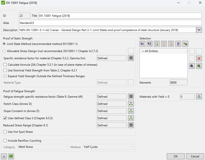
Press  to Set Standard Custom Settings
EN 13001-3-1 standard deals only with the limit state method. The allowable stress method is reliable in specific cases - for cranes where all masses act only unfavorable with a linear relationship between load actions and load effects.
Static Strength
For static strength, the default method is the Limit State Method. If the Allowable Stress design method is used press
 to specify safety factors for Individual Loads and Load Sets. The limit design stress for normal stresses:

For shear stresses:

Where 
 is the general resistance factor (EN13001-2).
 is the specific resistance factor for the material.
Press  to define characteristic with specific resistance factor.
In case of plane states of stresses when von Mises stresses are not used it shall additionally be proven that:

Use Nominal Yield Strength from Table 2, Chapter 4.2.1 - use the nominal yield strength values for plate elements as defined in Table 2, Chapter 4.2.1 that depend on type of material and a plate thickness. Otherwise, take yield stress defined in the Materials.
Note: for beams and solids the yield stress value is always used, ignoring the option.
Expand Yield Strength Outside the Defined Thickness Ranges - Use first or last Nominal Yield Strength available in the Table 2, Chapter 4.2.1 if the plate thickness is outside the defined ranges in the table. Otherwise 12345678 will be used.
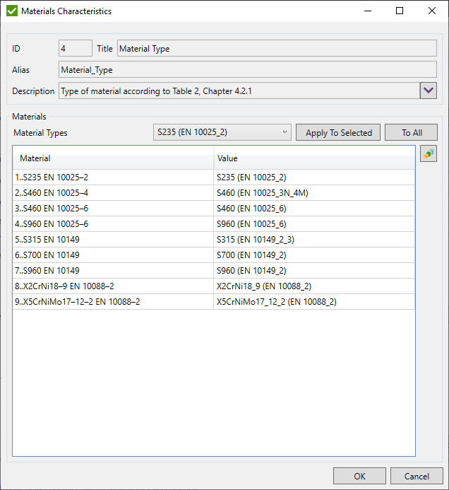
Material Type - press  to define type of material from Table 2, chapter 4.2.1 to get the nominal yield strength:
Fatigue Strength
Fatigue Strength can be calculated using 2 methods: Direct Use of Stress History and Simplified Method (Chapter 6.5.3).

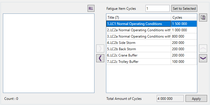
In the direct use of stress history method Stress History Parameter is calculated automatically based on stress ranges and stress history (Fatigue Group):
Example: Fatigue Group with a total amount of cycles 4 million:
Stress History Parameter:

| ν | is the relative total number of occurrences of stress ranges; |
| km | is the stress spectrum factor dependent on m; |
| Δ σi | is the stress range i; |
| Δ^σ | the maximum stress range; |
| ni | is the number of occurrences of stress range i; |
 | is the total number of occurrences of stress ranges during the design life of the crane; |
| m | is the slope constant of the logΔσ—logN -curve of the component under consideration. |
The limit design stress for fatigue

| ΔσRd | is the limit design stress range |
| Δσc | ia the characteristic fatigue strength (see Annex D and Annex H) |
| m | is the slope constant of the ogΔσ—logN curve (see Annex D and Annex H) |
| ϒmf | is the fatigue strength specific resistance factor (see Table 9) |
| sm | is the stress history parameter |
The combined fatigue effect of normal and shear stresses:

Note: Maximum value between each combination (x^2 + xy^2 + xz^2, y^2 + xy^2 + yz^2, z^2 + yz^2 + xz^2) will be taken as a result of formula 41.
Check with the simplified method is optional, stress history parameter is user input and fatigue is calculated for one stress range (Load Group) without summation.
For Fatigue strength resistance factor, notch class, slope factor, and reduced stress range have to be defined.
Fatigue strength specific resistance factor is an elemental characteristic. Chapter 6.1 Table 9:
| Accessibility for inspection | Fail-safe detail | Non fail-safe detail | |
|---|---|---|---|
| Without hazard for personsb | With hazard for persons | ||
| Detail accessible without disassembly | 1.0 | 1.05 | 1.15 |
| Detail accessible by disassembly | 1.05 | 1.10 | 1.20 |
| Non-accessible detail | N/A | 1.15 | 1.25 |
Notch Class and Slope Factor should be defined for different direction: X - parallel to the weld, Y - perpendicular, XY - Shear based on Annex D.
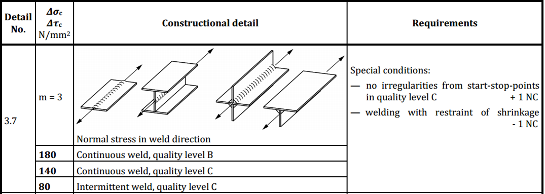
 - define Notch class.
Example of classification:
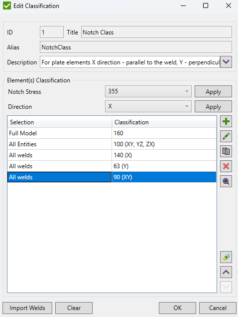
 - clear classification results.
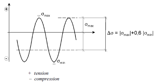
In non-welded details or stress-relieved welded details the effective stress range may be calculated by adding the tensile portion of the stress range and 60% of the magnitude of the compressive portion of the stress range:
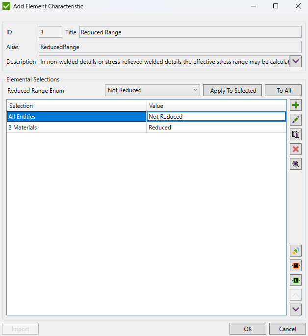
By default, the Reduced Range is set to Not Reduced. Press  to specify the selection which should use reduced stress range:
Standard uses material data (Yield/Tensile) in calculations. Wizard checks if the values are defined for all materials.
Use Hot Spot Stress - use Hot Spot Stress results for locations defined in Weld Finder Tool or Weld Stress results in the fatigue checks.
Include Rainflow Counting - include rainflow fatigue summation check with defined result category and method from which Rainflow Counting data will be used.
Note: category options for fatigue are Weld Stress or Hot Spot Stress.
Note: this option is available only for Enterprise licensing.
