AISC 360-10 Members (14th, 2010)
AISC 360-10 (14th, 2010) - an American national standard "Specification for Structural Steel Buildings" released in June 22, 2010. Checks are performed according to the provisions for the load and resistance factor design (LRFD) and Allowable Strength Design (ASD).
This Standard implements checks for the design of members for tension, compression (Chapter D and E including Torsional and Flexural-Torsional Buckling), bending (Chapter F), shear (Chapter G) and combined (Chapter H) and supports double symmetric I-beams, single symmetric Channels, Circular, double symmetric Rectangular tubes, Circular and Rectangular bars.
To add the standard execute from the ribbon:
![]()
Press  to Set Standard Custom Settings
To see what elements are not verified for all checks or bending checks according to AISC 360-10 press .
It is possible to check the design according to the load and resistance factor design (LRFD) or Allowable strength design (ASD). The difference between these 2 designs is in the load combinations and resistance factors:
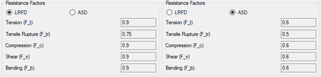
According to the standard Design Strength is multiplied on LRFD factor and divided on ASD factor for tensile yielding in the gross section:
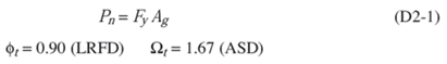
In SDC Verifier multiplication is always used. ASD factor are converted to 1 / Sf (ASD). For example, a tensile resistance factor (F_t) = 1 / 1.67 = 0.6.
Press  to set Section Build Type (rolled or built up).
![]()
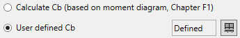
Lateral-torsional buckling modification factor (Cb) can be calculated based on moment diagram of beam member or defined manually. By default user defined option is used and Cb is set to 1 (conservative):
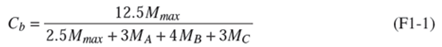
where
| Mmax | = absolute value of maximum moment in the unbraced segment, kip-in. (N-mm) | |
| MA | = absolute value of a moment at a quarter point of the unbraced segment, kip-in. (N-mm) | |
| MB | = absolute value of a moment at a centerline of the unbraced segment, kip-in.(N-mm) | |
| MC | = absolute value of a moment at three-quarter point of the unbraced segment, kip-in. (N-mm) |
For cantilevers or overhangs where the free end is unbraced, C b = 1.0.
Note: For the doubly symmetric members with no transverse loading between the brace points, Equation F1-1 reduces Cb to 1.0 for the case of equal end moments of the opposite sign (uniform moment), 2.27 for the case of equal end moments of the same sign (reverse curvature bending), and to 1.67 when one end moment equals zero. For singly symmetric members, a more detailed analysis for Cb is presented in the Standard Commentary.
For Shear Check for webs with the transverse stiffeners it is required to define a clear distance between the transverse stiffeners (Chapter G2.1):
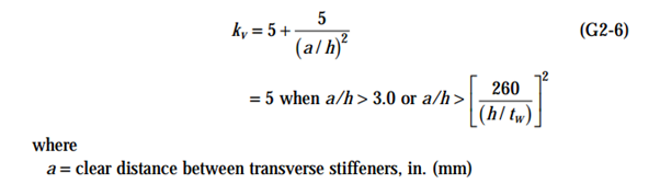
If members are recognized stiffener distance is set to the members length from torsional direction:
![]()
According to the calculation procedure, Beam Length for Y and Z direction is required. Data from Beam Member Finder is used automatically.
If beam members are not recognized press  .
.
Standard uses material data (Yield/Tensile) in calculations. Wizard checks if the values are defined for all materials.
Calculate asymmetric shapes as symmetric - minimum sizes of walls/flanges will be used to calculate cross-section properties (area, moments of inertia etc.). Option works within the current standard.
Note: Execute from the tree to transform asymmetric I-beams, Channels or Rectangular tubes to symmetric for the full project.
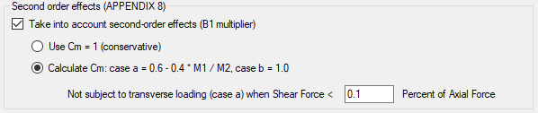
It is possible to take into account second order effects (see explanation in AISC 360-10, Appendix 8):
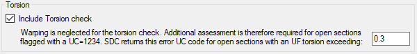
To include a Torsion check set option Include Torsion check ON.
For torsion the check warping is neglected and if Utilization Factor for torsion exceeds 0.3, the warning code 1234 is set to UF. Additional assessment for torsion is required:
AISC 360-10 can be used in a combination with API RP 2A-LRFD (1st, 1993) standard. Set the option
Use API 2A RP for tubular shapes checked to use the standard for circular tubes. Press
 to define settings.
Note: If the API 2A RP is included - 3 standards will be created:
- AISC 360-10 - all supported shapes are calculated according to AISC 360-10;
- API RP 2A-LRFD - circular tubes are calculated according to API LRFD;
- AISC and API - combined standard where results for circular tubes are taken from API RP 2A-LRFD and results for other supported shapes - according to AISC 360-10.
To verify the model create table for Overall Check:
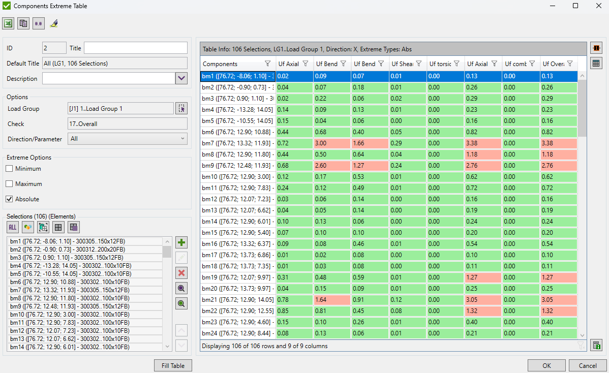
All Checks have Utilization Factor parameter = (Force, Moment, etc.) / Design Strength. It should be below one (<1) then the check passes.
The value 12345678 is used when the calculations cannot be performed due to geometrical limitations or calculations are out of scope.
Press  to display calculation details (stress calculations, all formulas) for the worst element of selected selection.
Note: Elastic Section Modulus (S) is calculated using a moment of inertia. Fillets are ignored and to get more accurate results a moment of inertia should be adjusted. Plastic Section Modulus is counted ignoring fillets which in results gives ~1-2% difference.
In Shear Check for circular tube equation G6-2a is not used, because it is not possible to define Lv automatically - distance from maximum to zero shear force. It cannot be defined by user as it is different for each individual load.
The Nominal Shear Strength for the circular tubes equals Minimum of G6-2b and Shear Yielding (0.6 * Fy)
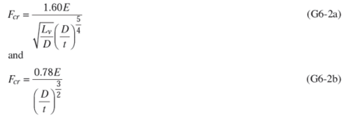
but shall not exceed 0.6 Fy
Note: The shear buckling equations, Equation G6-2a and G6-2b, will control D/t over 100, high-strength steels, and long lengths. For the standard sections, shear yielding will usually take control.