Eurocode3 Members (EN1993-1-1, 2005)
Eurocode 3 - member checks according to Eurocode3: Design of steel structures - Part 1-1: General rules and rules for buildings (May 2005). Chapter 6 "Ultimate limit states" is implemented.
Note: Checks are performed for I-beams, Channels, Tee, Circular and Rectangular tubes, Circular and Rectangular bars
To add the standard execute from the ribbon:
To see what elements are not verified for all checks or bending checks according to Eurocode 3 Member Checks press .
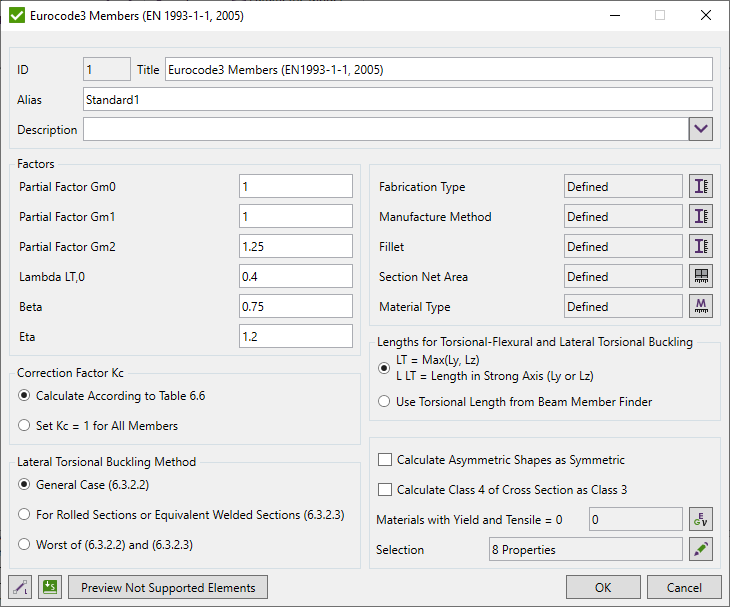
Press  to Set Standard Custom Settings
Resistance Partial Factors:
Gm0 - resistance of cross-sections whatever the class is;
Gm1 - resistance of members to instability assessed by member checks;
Gm2 - resistance of cross-sections in tension to fracture.
Partial Factors can be defined by National Annex. The following values are recommended.
γm0= 1,00
γm1= 1,00
γm2= 1,25
The parameters for λLT,0 and β are given in the National Annex. The following values are recommended for rolled sections or equivalent welded sections:
The plateau length of the lateral torsional buckling curves for rolled sections:
λLT,0 = 0,4 (maximum value)
The correction factor for the lateral torsional buckling curves for rolled sections:
β = 0,75 (minimum value)
Eta (η) is used in the shear area calculations (may be taken from the National Annex). The default value is 1.2.
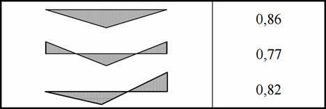
A correction Factor Kc can be calculated using the Cm Tool for each member. Also it is possible to set the Kc equal to 1:
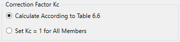
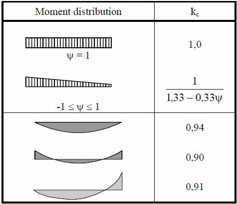
Table 6.6: The Correction Factor:
The following cases are NOT recognized and are skipped:
For the properties the following characteristics should be defined:
- Fabrication Type - Rolled or Welded;
- Manufacture Type - Hot Finished or Cold Formed;
- Fillets have to be defined in the characteristic (if they are missed in the model);
- Section Net Area - for fasteners with holes net area has to be defined;
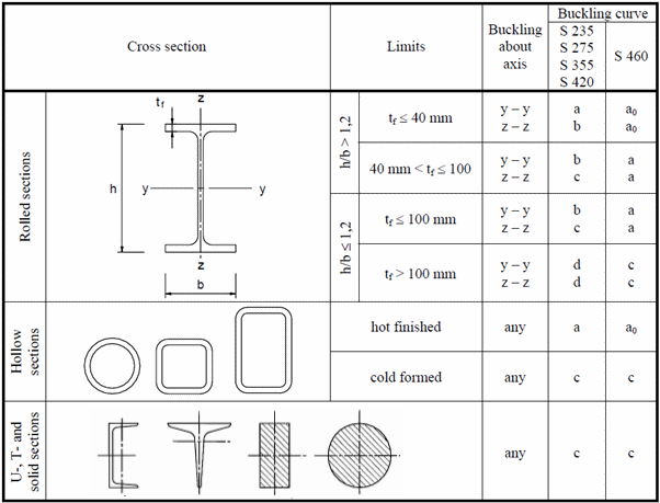
- Material Type - the buckling curve (Table 6.2) depends on the material type. Material s460 has different classification then the other types.
Note: For rolled section fillets are taken into account in the classification and shear calculations from the characteristic. For more accurate results, modify the shape area and the moment of inertia in the model to take into account fillets.
Standard uses material data (Yield/Tensile) in calculations. Wizard checks if the values are defined for all materials.
Calculate asymmetric shapes as symmetric - minimum sizes of walls/flanges will be used to calculate cross-section properties (area, moments of inertia etc.). Option works within the current standard.
Note: Execute from the tree to transform asymmetric I-beams, Channels or Rectangular tubes to symmetric for the full project.
Calculate Class 4 of cross section as Class 3 - recalculate maximum possible yield stress so that cross section will pass the limits of Class 3 and use new yield stress in further calculations. Option works within the current standard.
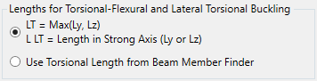
Member Length for Torsional and Torsional-Flexural Buckling Check (LT) by default is max among Ly and Lz lengths. For lateral torsional buckling (L LT) is length in strong axis:
Data from Beam Member Finder is used automatically.
If beam members are not recognized press  .
.
Note: Effective Length Factor for both options is taken from Length Torsional - Length Factor.
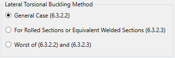
It is possible to choose the calculation method for Lateral Torsional Buckling: General Case (chapter 6.3.2.2), For rolled sections or equivalent welded sections (chapter 6.3.2.3) or the worst of two (min reduction factor is used from 2 methods):
Formulas
Eurocode3 Member Checks support verification of the sections that belongs to Class 1-3, Class4 is out of the scope.
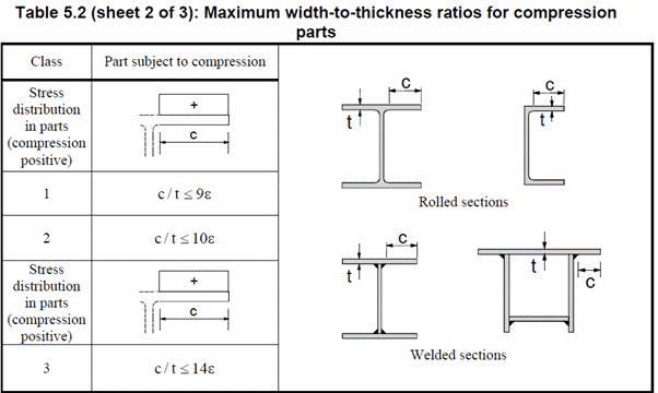
Cross Section Class:
The role of cross section classification is to identify the extent to which the resistance and rotation capacity of cross sections is limited by its local buckling resistance.
Web Classification:
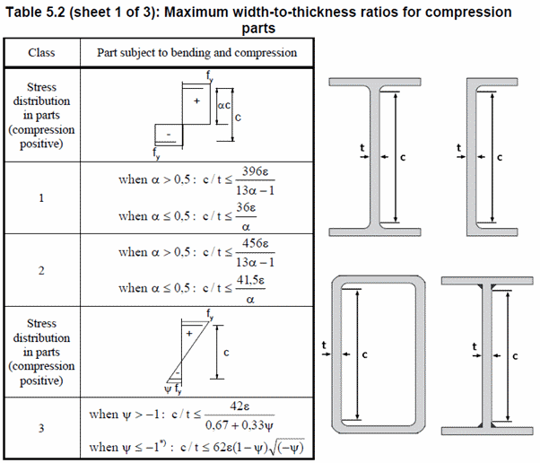
A Compression portion of the web in the case of a plastic stress distribution:
The ratio of end stresses in the case of an elastic stress distribution:
Both parameters are calculated according to the Appendix: Chapter 5.5 (Steel Designers' Manual, 7th edition)
Flange Classification:
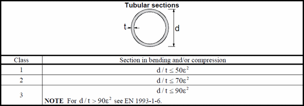
For the circular tubes:
Tension and Compression
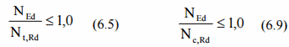
The Axial design force should satisfy the following condition (6.5) for tension and (6.9) for compression:
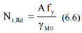
The Axial resistance for tension:
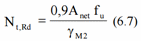
The Axial resistance for fasteners with holes (min (6.6) and (6.7)):
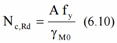
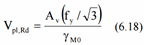
Axial resistance for compression:
Bending Moment
Design bending moment should satisfy the following condition:
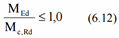
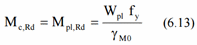
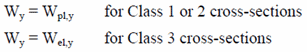
The Bending moment resistance for class 1 and 2:
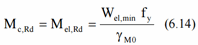
For the class 3:
For class 1 and 2 bending moment resistance is calculated using the Plastic Section Modulus, it is calculated in SDC Verifier without taking into account fillets. The bending resistance in result is a bit lower (conservative) for the sections with class 1 and 2. For class 3 resistance is calculated based on the elastic section modulus. Modify the shape moment of inertia to take into account fillets in order to achieve more accurate results.
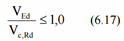
Shear
Shear force should satisfy following condition:
Shear resistance:
Av - shear area.
Rolled I-Beam:
Web Area: A-2btf + (tw + 2r)tf but not less than ηhwtw
Flange Area: Σ(hwtw)
Welded I-Beam:
Web Area: ηΣ(hwtw)
Flange Area: A-Σ(hwtw)
Rolled Channel:
Web Area: A - 2btf + (tw + r)tf
Flange Area: Σ(hwtw)
Welded Channel:
Web Area: Σ(hwtw)
Flange Area: A-Σ(hwtw)
Rolled Rectangular Hollow Sections: Ah/(b+h)
Welded Rectangular Hollow Sections:
Web Area: ηΣ(hwtw)
Flange Area: A - Σ(hwtw)
Circular Hollow Sections: 2A/π
Circular Bar Sections: 9/10A
Rectangular Bar Sections: 5/6A
Rolled Tee:
Web Area: A - btf + (tw + 2r)tf / 2
Flange Area: 0.83btf
Welded Tee:
Web Area: tw(h - tf / 2)
Flange Area: 0.83btf
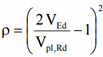
Where the shear force is more than half the plastic shear resistance its effect should be taken into account by using Reduced Yield Stress:
Fy = (1-ρ)fy
Note: The reduced value of Fy (Yield Stress) will be used throughout all cross-section checks (clause 6.2).
Bending and Axial Checks
For the class 1 and 2 the following condition should be satisfied:
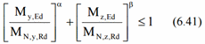
For the class 3 and the channel (all classes):
I Section: α = 2; β = 5n but β≥1
Circular tubes: α = 2; β = 2
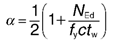
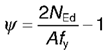
Rectangular tubes: 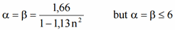
n - axial utilization factor (6.5 or 6.9).
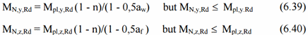
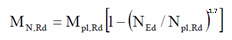
Mn,y,Rd and Mn,z,Rd - the design plastic moment resistance reduced to the axial force Ned.
I-Beams:
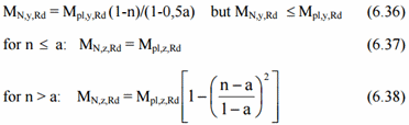
Rectangular Tubes:
Circular Tubes:
Buckling resistance in compression
Compression member should be verified against the buckling as follows:
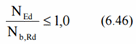
Axial Buckling Resistance:
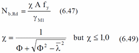
Where
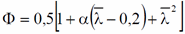
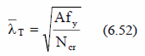
Non-dimensional slenderness:

Elastic Critical Force:

Table 6.1: Imperfection factors for buckling curves:
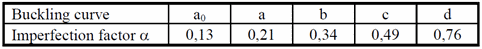
Table 6.2: Selection of buckling curve for a cross-section
Torsional and torsional-flexural buckling
For I-beams and channels torsional or torsional-flexural buckling check should be performed.
Non-dimensional slenderness:
Where Ncr = Ncr, TF but Ncr < Ncr, T
Ncr, TF, is the elastic torsional-flexural buckling force;
Ncr, T, is the elastic torsional buckling force.
Buckling Resistance in Bending
A laterally unrestrained member subject to the major axis bending should be verified against the lateral-torsional buckling as follows:

Square or circular hollow sections, fabricated circular tubes or square box sections are not susceptible to the lateral-torsional buckling.
Buckling Bending resistance:
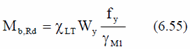
Wy - an appropriate section modulus:
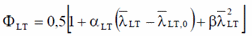
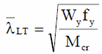
Reduction factor for rolled sections and equivalent welded sections (6.3.2.3):
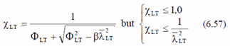
Value to determine reduction factor:
The parameters λLT,0 and β may be taken from the National Annex. The following values are recommended for rolled or equivalent welded sections:
λLT,0 = 0,4 (maximum value)
β = 0.75 (minimum value)
To take into account the moment distribution between the lateral restraints of members the reduction factor can be modified as follows:
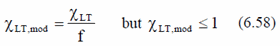
Modification Factor:
f = 1 - 0,5(1-kc)[1-2,0(λLT,0-0,8)2] but f ≤1,0
Kc is the correction factor according to the Table 6.6.
Reduction Factor - general case (6.3.2.2):
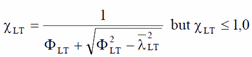
Value to determine reduction factor:
Non-dimensional slenderness for lateral-torsional buckling:
Mcr - elastic critical moment for lateral-torsional buckling.
DESIGNERS' GUIDE TO EUROCODE 3:
DESIGN OF STEEL BUILDINGS
EN 1993-1-1, -1-3 and -1-8
Second edition
LEROY GARDNER and DAVID A. NETHERCOT
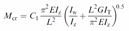
For I-beam and channel Mcr is calculated (according to the Designers' guide to Eurocode3: Design of steel buildings, 2nd edition):
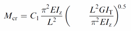
For Rectangular tubes:
C1 is calculated using the following formula:

Note: SDC Verifier calculates Mcr for case when load application is in the shear centre (centroid for double symmetric shapes) Zg = 0:
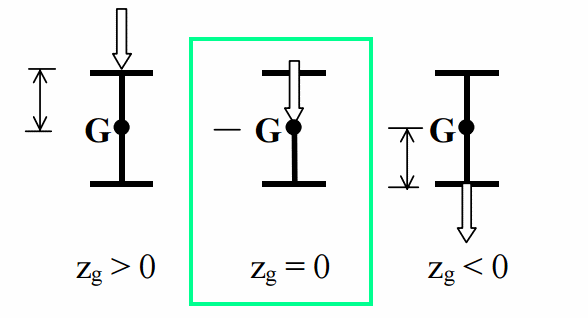
For cases when Zg > 0 the torsional stability is reduced. A plate model is necessary to take into account this effect.
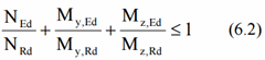
Bending and Axial Compression
The members which are subjected to the combined bending and the axial compression should satisfy the following equations:
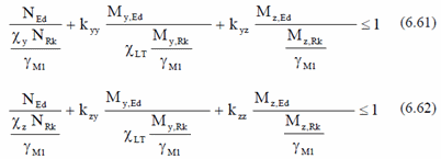
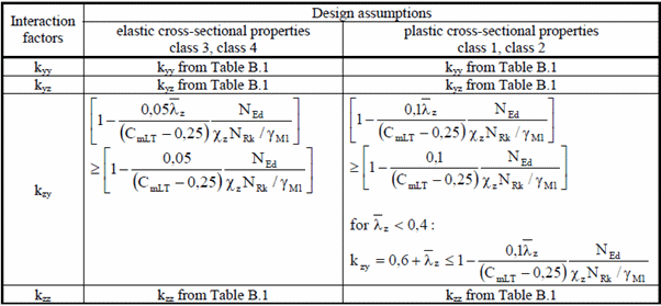
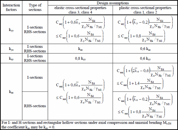
Interaction factors kyy, kyz, kzy, kzz are calculated based on the Method 2 from the Annex B:
The Table B.1: Interaction factors kij for the members not susceptible to the torsional deformations:
The Table B.2: Interaction factors kij for the members susceptible to the torsional deformations: