DNV RP-C201 Plate/Stiffener Buckling (2010)
DNV RP-C201 Plate/Stiffener Buckling (2010) verifies structural stability for each structural member (plate and stiffener). Chapter 6: Buckling of unstiffened plates and chapter 7: Buckling of stiffened plates are implemented.
To add the standard execute from the ribbon:
Press  to Set Standard Custom Settings
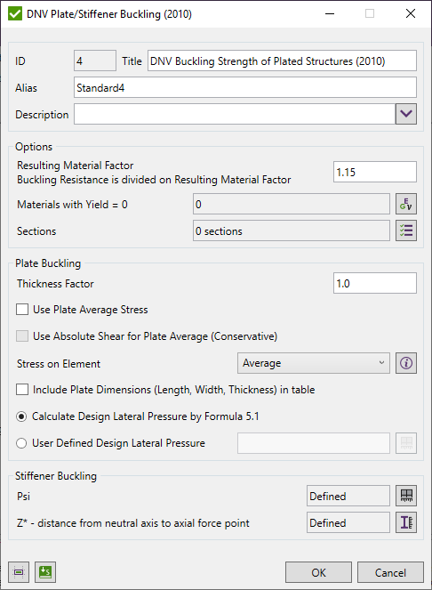
Resulting Material Factor - critical buckling stresses are divided on Resulting Material Factor.
Standard uses material data (Yield/Tensile) in calculations. Wizard checks if the values are defined for all materials.
Plate and Stiffener Buckling Checks are calculated on Sections. With the help of Panel Finder tool, it is possible to automatically recognize Section and Plates with their dimensions.
By default, All Sections are included in the selection but can be changed by pressing  . If sections were not recognized press
  to run Panel Finder tool.
Plate Buckling options
Thickness Factor - increases each plate thickness (e.g. 1.1 increase on 10%) and decreases stresses;
Calculations are performed for each element with converted stresses (into plate direction) or Plate Average Stresses and using Plate dimensions.
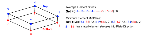
Stress on Element - what stress to check.
Average - average stress among element point of interests.
Min Midplane - minimum midplane stress (Stop + Sbottom / 2), without bending.
Use Absolute Shear for Plate Average - used only together with plate average option and means that absolute shear is used for plate averaging:
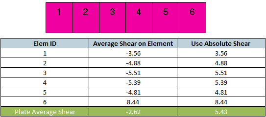
With Absolute Shear option, higher shear stress is used for checking, that makes verification more conservative.
Include Plate Dimensions in the table - set parameters Length, Width and Thickness to be included in the table.
Calculate Design Lateral Pressure by formula 5.1 - calculates Design Lateral Pressure by formula:
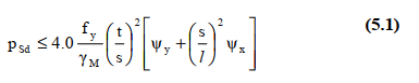
User Defined Design Lateral Pressure - set Design Lateral Pressure of plates manually.
Stiffener Buckling options
Psi - ratio of smaller to larger design stress in the transverse direction (tensile taken as positive). SDC Verifier uses averaged plate stresses but it is possible to manually set Psi for selected elements:
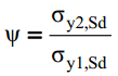
Z* - is the distance from the neutral axis of the effective section to the working point of the axial force. By default, the simplification is used and z* = 0. It is possible to set z* for different sections. Set z* to 12345678 to use z* equal to zp. See Commentary to 7.7 Interaction equations for axial compression and lateral pressure in DNV-RP-C201 2010 for details.
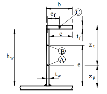
Plate Buckling Calculation
For the individual loads and loads sets, plate buckling is calculated basing on the formulas using stresses from the load. For Load Group the plate buckling is calculated as an envelope. Load Group items are calculated using formulas and then min/max/abs (among the items buckling results) is found. Load Group contains the worst values for each parameter and gives a possibility to check the highest Ultimate Strength and Buckling State Limits for all items at once.
Ultimate Strength Limit and Buckling State Limit depend on the plate results (stresses) and plate dimensions (length, width and thickness).
Plate buckling check includes various options for stresses to be checked:
- Element Stress: MidPlane (no bending) or Average;
- Use Plate Average Stress - the stress is averaged on the plate using elements area. The calculation is performed on every element but with averaged plate stresses.
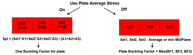
- Use Absolute Shear for plate average (Conservative);
Note: For x and y directions only compression (negative) stresses are used in calculations. Positive stress is ignored and set to 0. For shear (xy) direction positive and negative stresses are used.
Stress Conversion
Plate Buckling check requires to verify element stresses (Sx, Sy and Txy) to be translated into the plate X, Y, XY directions.
Conversion of the stresses is done automatically in Plate Buckling check. For the element average option - the nodal element stresses at top and bottom are averaged (which is equivalent to using midplane centroid stress) and translated into plate directions. For Min Midplane option - the midplane stresses are translated into the plate directions and then the minimum values are taken.
Plate Dimensions and Thickness
Results depend on the plate dimensions and direction. It is important to understand how the Panel Finder performs recognition. Length is considered to be the longest edge of the plate and width the longest perpendicular to the longest edge:
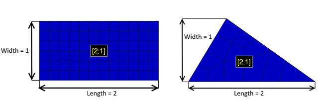
Plate dimentions can be calculated using CSR method - calculate equivalent rectangular plate dimensions described in Common Structural Rules (1 Jan 2018) Part 1, Chapter 8, Section 4 (2.3)
Calculations are performed on every element and thickness is taken directly from each element. It is possible to set thickness manually, in this case, element thickness will be ignored and user-defined thickness will be used.
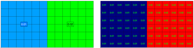
Example: A Plate with 2 properties 0.01 and 0.02 thicknesses. The left picture displays the property labels with property thicknesses and the right one presents plate buckling plot of thickness parameter:
Formulas
The design buckling resistance of an unstiffened plate under longitudinal compression force may be calculated as:
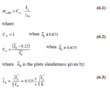
in which
s = plate width
t = plate thickness
fcr = critical plate buckling strength
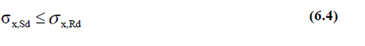
The resistance of the plate is satisfactory when:
The design buckling resistance of a plate under transverse compression force may be found from the following formulas:
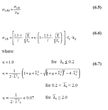
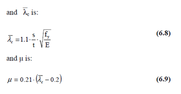
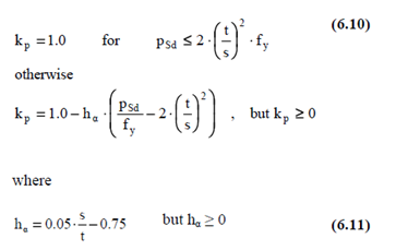
The reduction factor due to lateral load kp may, in lieu of more accurate results, be calculated as:
The resistance of the plate is satisfactory when:

Shear buckling of a plate can be checked by

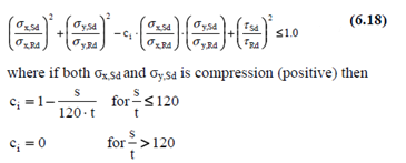
A plate subjected to biaxial loading with shear should fulfill the following requirement:
Stiffener Buckling Calculation
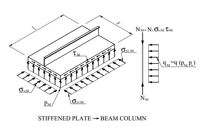
Stiffened plates subjected to combined forces should be designed to resist an equivalent axial force Nsd (7.1) and an equivalent lateral load Qsd (7.8).
Three types of stiffeners are supported: L, T and Flat bars.
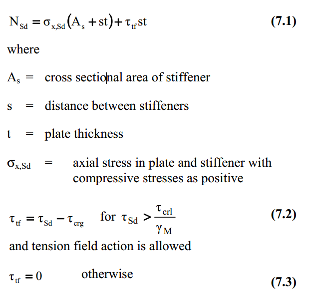
Equivalent Axial Force
Equivalent Force is calculated based on averaged stiffener axial force, averaged plate stresses in X direction (parallel to the stiffener) and tension field action.
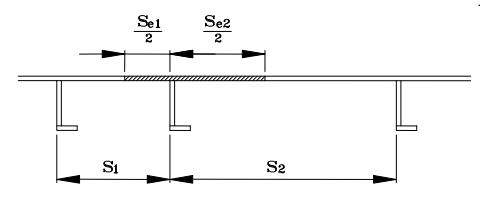
Plate Stresses are calculated on half of plates elements connected to the stiffener:

Dimensions. Stiffener Length, Girder Length and Torsional Length are recognized by Panel Finder. For the plate thickness - the minimum thickness is taken from all connected plates to the stiffener. The distance between stiffeners - average plate width perpendicular to the stiffener calculated in Panel Finder.
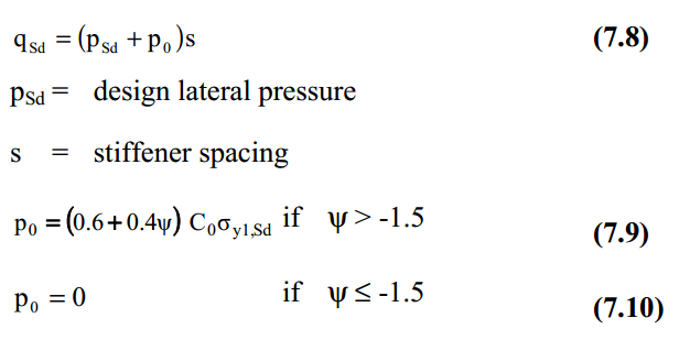
Equivalent Lateral Line
Sum of design lateral pressure and equivalent lateral pressure multiplied on stiffener spacing (averaged plate width):
Note: If not all the elements local axes are oriented perpendicularly to the plate (Y or Z) the value 12345678 is used.
Design lateral pressure is calculated as different between maximum shear forces on stiffener ends and divided on area (stiffener length * stiffener width).
Equivalent lateral pressure is calculated using formula 7.9 with ψ = 1. It is possible to modify it using characteristic.
Effective plate width and η
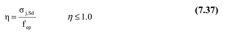
Effective plate width is calculated according to 7.13 by a separate tool (Effective Width under tools) for each plate connected to the stiffener. The average effective plate width is used.
Effective Width tool also calculates η factor (7.37) which is used to calculate Beta coefficient in chapter 7.5.2 Torsional Buckling of stiffeners:
Shear force should satisfy the following condition:
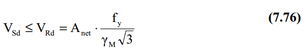
Shear force perpendicular to the plate is checked for each stiffener element. If not all the elements local axes are oriented perpendicularly to the plate (Y or Z) the value 12345678 is used.
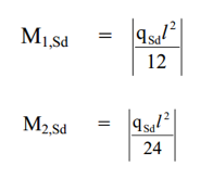
Bending Moments are calculated based on Equivalent Lateral Line. They are used in chapter 7.7. Interaction formulas for axial compression and lateral pressure:
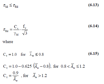
Resistance of stiffened panel to shear stresses is calculated according to Chapter 7.6:
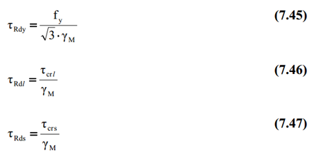
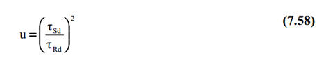
Plate average shear stresses are compared to τRd = Min(τRdy, τRdl, τRds):
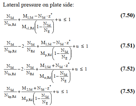
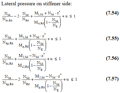
The following interactions formulas for axial compression and lateral pressure according to Chapter 7.7 are calculated. For continuous stiffeners equations the maximum value of (7.50-7.53) - lateral pressure on plate side and (7.54-7.57) - lateral pressure on stiffener side is checked:
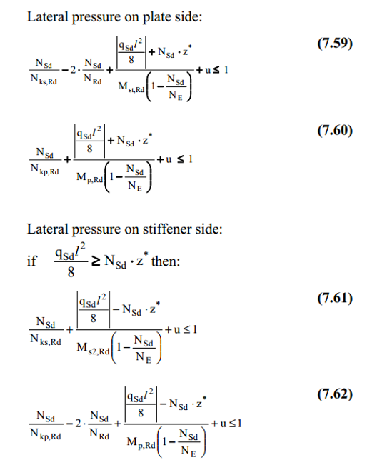
For sniped stiffeners the maximum value of (7.59-7.60) - lateral pressure on plate side and (7.61-7.62) - lateral pressure on stiffener side is checked: