FKM (6th, 2012)
FKM (6th, 2012) – analytical strength assessment of components in mechanical engineering.
To add FKM (6th, 2012) standard execute from the ribbon:
Press  to Set Standard Custom Settings
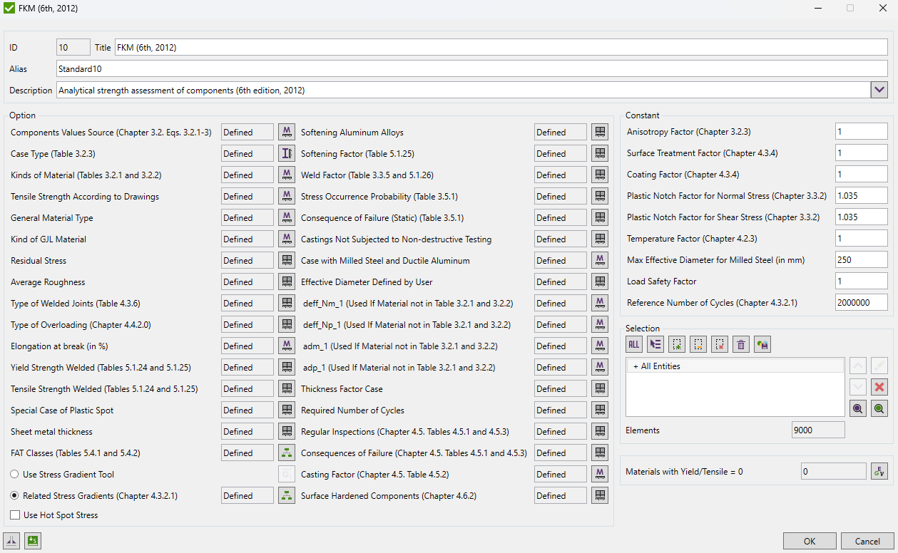
Components Values Source - Chapter 3.2.1. Component values according to standards. Equations (3.2.1-3).
Case Type - Used for defining effective diameter according to Table 3.2.3.
Kinds of Material - Kinds of material for defining constants d_effN and a_d according to tables 3.2.1 and 3.2.2.
Tensile Strength According to Drawings - material tensile strength, Rmz. If Components Values Source defined as Standard this parameter will not be used in the calculations.
General Material Type - the type of material, used for Fatigue Strength Factors.
Kind of GJL Material - type of GJL material. Will be taken into account only in case of GJL Material type.
Residual Stress - High/Medium/Low to get residual stress factors. Table 4.4.2.
Average Roughness - for polished surfaces Rz = 1 (in micrometers).
Type of Welded Joints - used for calculation of Thickness Factor. Table 4.3.6.
Type of Overloading - used in determining the mean stress factor KAK. Chapter 4.4.2.0.
Elongation at break - elongation at break A, in %. Table 5.1.2.
Yield Strength Welded - static yield stress at welded components.Tables 5.1.24 and 5.1.25.
Tensile Strength Welded - static tensile strength at welded components.Tables 5.1.24 and 5.1.25.
Special case of plastic spot - use formula 3.3.7 for zones surrounded by a large elastic area resulting in a very high plastic limit.
Sheet metal thickness - Thickness of the sheet metal (should be defined in case of non plate/shell element types) for thickness factor calculation. In model units.
FAT Classes - FAT classes for welded parts according to tables 5.4.1 and 5.4.2. For non-welded parts 0 value should be set.
Related Stress Gradient - can be calculated automatically by Stress Gradient tool or defined by classification (Chapter 4.3.2.1). By default the value 0.01 i used.
Softening aluminum alloys - use formula 3.3.14 for softening aluminum alloys or formula 3.3.13 for steel and non-softening aluminum alloys.
Softening factor - softening factor. Table 5.1.25.
Weld factor - weld factor. Tables 3.3.5 and 5.1.26.
Stress occurrence probability - Probability of the occurrence of the stress or the stress combination. Table 3.5.1.
Consequence of failure (Static strength) - Consequence of failure. Table 3.5.1.
Castings Not Subjected to Non-destructive testing - Castings that have not been subjected to non-destructive testing. jG factor in formula 3.5.2.
Case with milled steel and ductile aluminum - omit proportions 1 and 3 in calculations of Total Safety Factor in formula 3.5.5 for milled steel or ductile aluminum in welded components.
Effective diameter defined by user - value is used in cases when effective diameter is not possible to be calculate automatically (e.g. for solid elements).
Constant d_eff_Nm_1 - used in case when material is not listed in the table 3.2.1 and 3.2.2.
Constant d_eff_Np_1 - used in case when material is not listed in the table 3.2.1 and 3.2.2.
Constant a_dm_1 - used in case when material is not listed in the table 3.2.1 and 3.2.2.
Constant a_dp_1 - used in case when material is not listed in the table 3.2.1 and 3.2.2.
Thickness factor case - Case A corresponds with the general wording of the IIW recommendations and shell be used if the user has no experience or no sector-specific experience is available which would justify the application of case B. Formulas 4.3.23-27
Required number of cycles - set required number of cycles for full model or for individual components separately.
Regular inspections - used in choosing of material safety factor jF. Chapter 4.5. Tables 4.5.1 and 4.5.3
Consequences of failure - used in choosing of material safety factor jF. Chapter 4.5. Table 4.5.1 and 4.5.3
Casting factor - casting factor jG. Chapter 4.5. Table 4.5.2
Surface hardened components - special cases of q value. Chapter 4.6.2
Use Hot Spot Stress - use Hot Spot Stress results for locations defined in Weld Finder Tool or Weld Stress results in the fatigue checks.
Constants
Anisotropy Factor - Anisotropy factor. Chapter 1.2.3. In case of multi-axial stresses and also with shear stresses. Material properties are same in all directions.
Surface Treatment Factor - Surface treatment factor. Chapter 4.3.4. without surface treatment and coating. Table 4.3.3 gives values of factors in case when treatment and coating influence should be taken into account
Coating Factor - Coating factor. Chapter 4.3.4. without surface treatment and coating. Table 4.3.5 gives values of factors in case when treatment and coating influence should be taken into account.
Plastic Notch Factor for Normal/Shear Stress - Plastic Notch Factor for Normal/Shear Stress. Chapter 3.3.2. Used only in case of GG material type.
Temperature Factor - Temperature factor. Chapter 4.2.3. For normal temperature is 1.
Max Effective Diameter of Milled Steel (in mm) - define the maximum possible diameter of milled steel in mm.
Load Safety Factor - load safety factor jS in case if load factors were added to load combinations.
Reference Number of Cycles - reference number of cycles of the fatigue class. Chapter 4.3.2.1.
Yield and Tensile
Standard uses material data (Yield/Tensile) in calculations. Wizard checks if the values are defined for all materials.