ISO 19902 (1st 2007)
ISO 19902 (1st, 2007) checks the structural strength and stability of tubular members.
This standard is applied to cylindrical members with Thickness ≥ 6mm, ratio D / t < 120 and Yield < 500 MPa.
To add the standard execute from the ribbon:
Press  to Set Standard Custom Settings
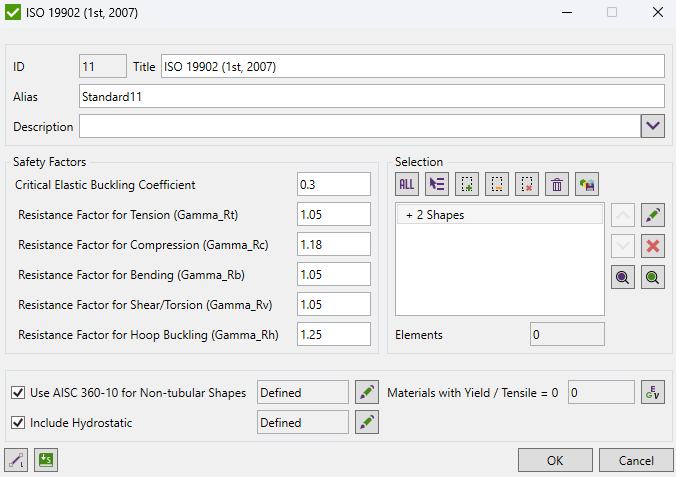
Safety Factors are set to Standard default values. It is not necessary to change them.
According to the calculation procedure, Beam Length for Y and Z direction is required. Data from Beam Member Finder is used automatically.
If beam members are not recognized press  .
.
Standard uses material data (Yield/Tensile) in calculations. Wizard checks if the values are defined for all materials.
It is possible to use ISO 19902 (1st 2007) in combination with AISC 360-10 Members (14th, 2010) standard.
Set option Use AISC 360-10 for non-tubular shapes checked to use the standard for non-tubular elements.
Press  to define settings.
Note: If the AISC 360-10 is included - 3 standards will be created:
- ISO 19902 - circular tubes are calculated according to ISO 19902;
- AISC 360-10 - all supported shapes are calculated according to AISC 360-10;
- AISC and ISO - combined standard where results for circular tubes are taken from ISO 19902 and results for other supported shapes - according to AISC 360-10.
To perform hydrostatic checks set option Include Hydrostatic to be checked and press to define options:
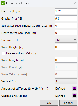
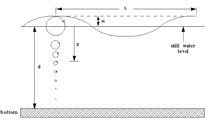
If model minimum coordinate in the vertical direction is 0 then Still Water Level = Depth to the sea floor;
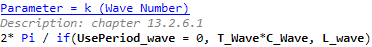
Instead of Wave Length, it is possible to define Wave Period and Wave Velocity:
Amount of stiffeners (stiffening rings) is used to calculate Lr (length of tubular):
Amount of stiffeners is defined as characteristic (for each beam member). By default amount of stiffeners equal to zero and torsional length recognized by Beam Member Finder is used for Lr:
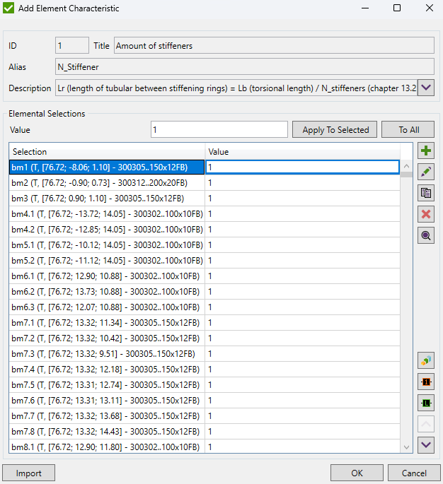
Capped End Actions - define 1 for elements when capped end actions should be included in calculations.
Joint Check
Joint Check is a part of the ISO 19902 standard but is available for Custom Standard. To create a new Joint Check execute from the checks context menu of a respective standard.
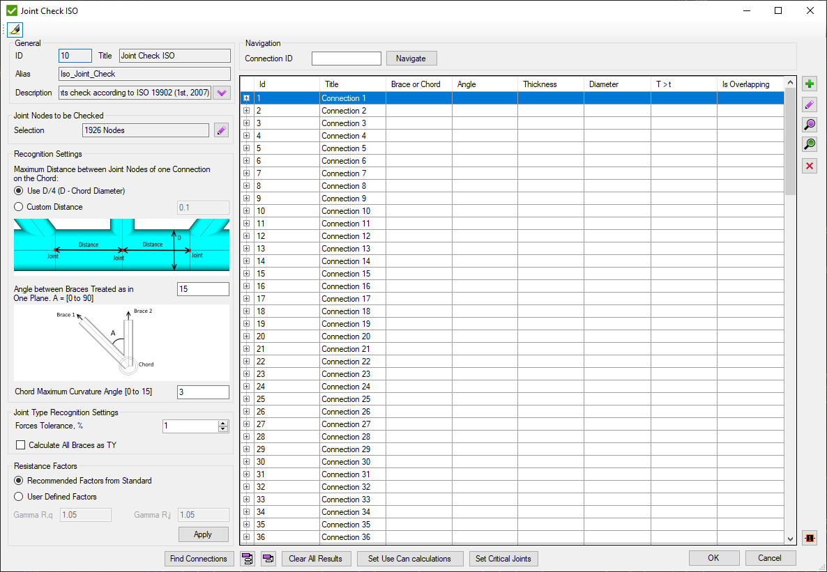
Press  to automatically highlight single Connection selected in the table.
Recognition Settings are described in Common Options chapter.
Resistance Factors - use recommended factors from the standard (= 1.05) or set custom factors (e.g. = 1)
Set Connection ID and press to display connection in the table.
Joint check is based on connections. Each connection is a set of elements near joint node (see Joints Finder). Connections consists of Chord and braces. Brace contains only 1 element with ID defined in brackets (#). Connection can contain braces from the both sides of the chord. Information is displayed in second brackets: U- upper braces; L- lower braces;
Press to find all connections of the model. Window with connections that are recommended to be checked manually will be displayed:
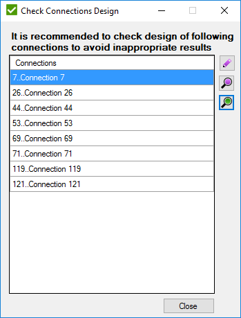
Connection has to be checked when:
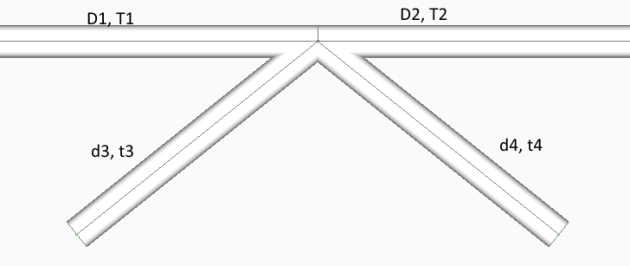
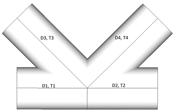
- D1 = D2 = d3 = d4, T1 = T2 = t3 = t4
- D1 = D2 = d4, T1 = T2 = t4, d3 > D1
- D1 = D2 = d3 = d4, T1 = T2 = t4, t3 > T1 according to the following image
 - Add new connection manually:
- edit selected connection;
 - preview highlight selected connection;
 - preview only selected connection;
 - remove selected connection;
 - plot all connections values in colors + Labels with IDs;
 - show information about all connections;
 - hide information of all connections.
![]() - clear all calculations for loads;
- clear all calculations for loads;
Edit Connection
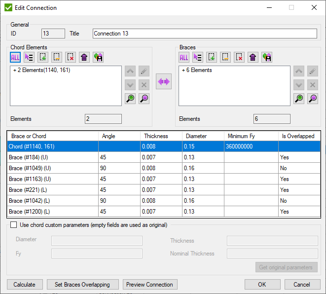
Pick Chord elements and braces (each brace consist of 1 element) and press to preview connection properties.
 - swap chord and brace selections
Press to highlight connection on the model.
- open window to set the overlapping brace. Is enabled only if one brace overlaps another one in connection:
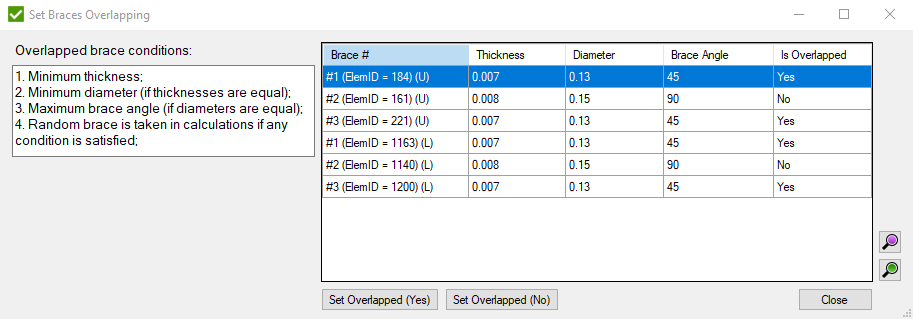
- set to the selected braces if they are overlapped.
 - set if brace is critical,
Ub (1 by default) and partial resistance coefficient (1.17 by default) to critical braces:
- set if brace is critical,
Ub (1 by default) and partial resistance coefficient (1.17 by default) to critical braces:
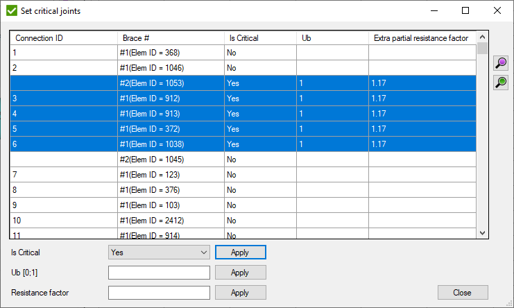
Select Is Critical and press to set if all selected braces are critical or non-critical.
Fill Ub and press to set Ub parameter to all selected braces.
Fill Resistance a factor and press to set a factor to all selected braces.
Note: Ub and Resistance factor are applied only to critical braces.
 - set if use can calculations (section 14.3.5) and effective length:
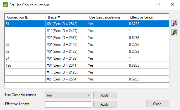
Select Use Can calculations and press to set if formula 14.3-11 will be applied to all selected braces.
Fill Effective Length and press to set the value to all selected braces.
Note: Effective Length is applied only to braces that Use Can calculations.
Joint Check Results
Mathematical background
All calculations are performed in accordance to ISO 19902 - First Edition 2007-12-01.
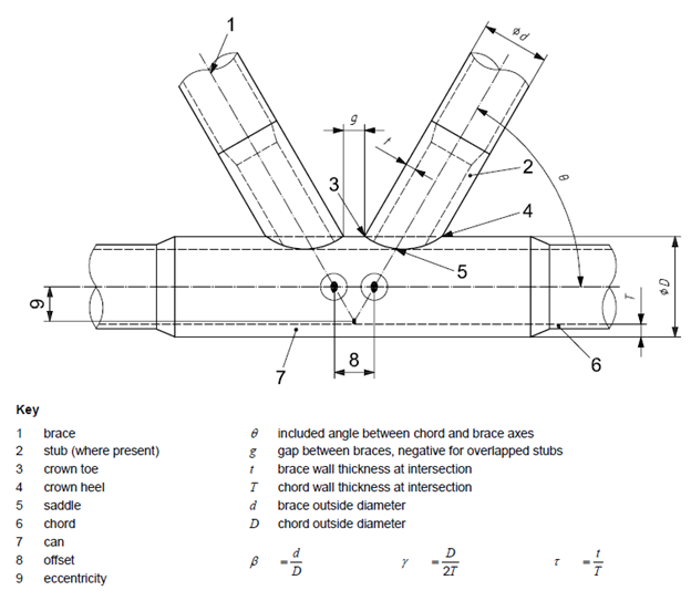
Nomenclature and geometric parameters that are used in results:
The validity ranges of connection parameters:
0.2 ≤ β ≤ 1.0
10 ≤ γ ≤ 50
30° ≤ θ ≤ 90°
τ ≤ 1.0
fy ≤ 500N/mm2
gT > -1.2γ
fy - chord allowable static stress = Min(yield stress, tensile strength * 0.8).
For each brace connected to the chord, connection elements of the chord are taken into account. Minimum allowable stress is taken if elements are of different materials.
Note: If material yield stress > 500 Mpa - allowable static stress is taken equal to material yield stress.
Brace Types. According to standard, joint types are defined by the following rules:
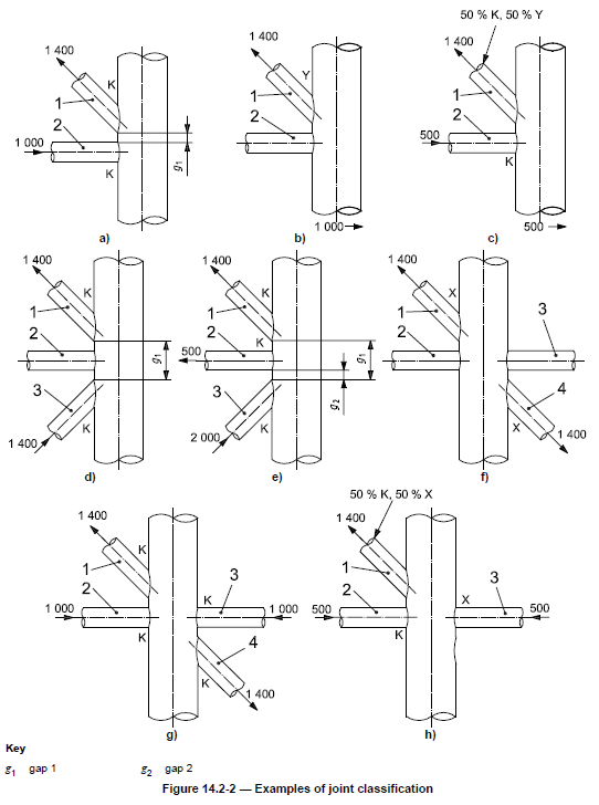
Joint type is based on type of loading. By checking if forces of connection are balanced joint types are classified on K, TY and X (Cross.
K - tension and compression loads are balanced.
TY - tension or compression load goes as a shear force in a chord.
X (Cross) - Connection has to contain braces from the both sides to check on a cross joint. If balanced forces of all braces on one side and balanced forces of all braces of other side are equal then all braces are classified as X (Cross).
Interpolation - the order of joint type recognition is following: K -> X (Cross) -> TY. Each brace can have all 3 types of the joint type taken as a percentage of the axial load of a brace to a summation of all braces loads.
Note: If brace has 0 force joint type for such brace is set to TY.
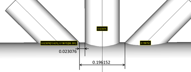
Gap calculations. The gap is a minimum distance between two differently loaded braces (tension and compression) measured on a shell of the chord.
Gaps depend on Load and are calculated only between the braces with different axial forces (tension and compression). Otherwise gap = 0.
Note: Overlapping braces can contain negative gap if they are loaded in a different way.
Note: It is possible that brace can have two or more gaps to considerate. Percentage of each gap is calculated using forces of the connection.
Basic Joint Strength.
Joint axial and bending capacities shall satisfy following equations:
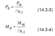
where
Pd - is the design value of the joint axial strength, in force units;
Md - is the design value of the joint bending moment strength, in moment units;
ΥRj - is the partial resistance factor for tubular joints, Upsilon;Rj = 1,05 ;
Strengths for simple tubular joints are calculated by following formulas:
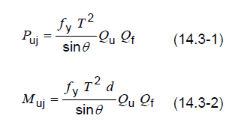
where
Puj - representative joint axial strength, in force units;
Muj - representative joint bending model strength, in moment units;
fy - representative yield strength of the chord member at the joint (SMYS or 0,8 of the tensile strength, if less), in stress units;
T - chord wall thickness at the intersection with the brace;
d - brace outside diameter;
θ - included angle between brace and chord;
Qu - strength factor;
Qf - chord force factor;
Strength factor Qu
Qu is the strength factor which varies with the joint and load type:
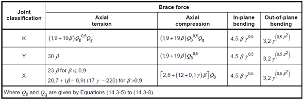
where
fy,b - representative yield strength of the brace at the intersection of the chord, in stress units;
t - brace wall thickness at the intersection of the chord;
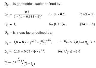
For -2.0 < g/T < 2.0, gap factor Qg is calculated as linear interpolation between formulas 14.3-7 and 14.3-8:
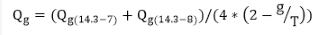
Note: g - total gap of the brace. From the following picture g = 0.023076 * 0.1362 + 0.196152 * 0.8638 = 0.172579;
Chord force factor Qf

where
λ = 0,03 for brace axial stress
= 0,045 for brace in-plane bending stress
= 0,021 for brace out-of-plane bending stress
qA parameter is calculated by the following formula:
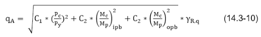
where
Pc - axial force in the chord member from factored actions;
Mc - bending moment in the chord member from factored actions;
Py - representative axial strength due to yielding of the chord member not taking account of buckling, in force units:
Py = A*fy
fy - representative yield strength of the chord member, in stress units;
A - cross-sectional area of the chord or chord can at the brace intersection;
Mp - representative plastic moment strength of the chord member;
Mp = We* fy,
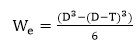 - plastic modulus;
D - chord member diameter;
T - chord member thickness;
ϒRq - partial resistance factor for yield strength, ϒRq = 1,05;
ipb - in-plane bending;
pb - out-of-plane bending;
C1 and C2 coefficients are taken from the table:
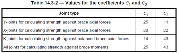
qA parameter is calculated for each chord member from the left and right side of intersection of a respective brace. Furthermore, axial forces are calculated for each brace type separately:
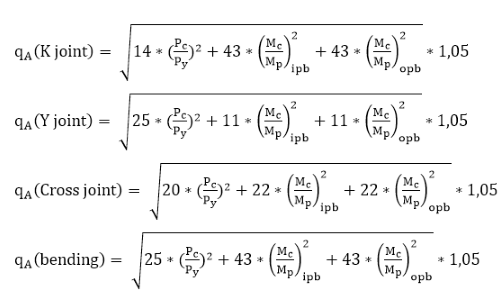
Maximum of left and right side chord members are taken into account:
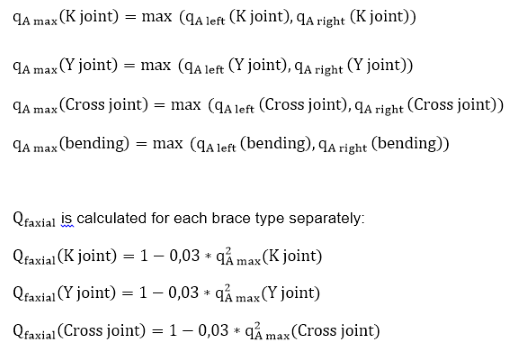
Qfaxial = Qfaxial(K joint)* brace percentage(K joint) + Qfaxial(Y joint)* brace percentage (Y joint) + Qfaxial(Cross joint)* brace percentage (Cross joint)
Qfipb = 1- 0.045 * q2A(bending)
Qfopb = 1- 0.021 * q2A(bending)
Extra joint axial capacity calculations are performed to connections that contain increased thickness of the chord. Axial strength is calculated by following formula:
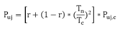
where
Puj- joint axial strength, in force units;
Puj,c - is the value Puj,c from Equation (14.3-1), based on the chord geometrical and material properties, including Qf calculated from chord can properties and dimensions;
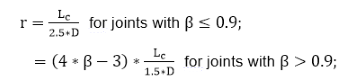
Note: r cannot be taken greater than 1;
Lc - effective total length;
Yn - the lesser chord member thickness on either side of the joint;
Tc - chord can thickness;
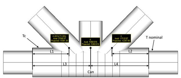
Effective length L is calculated for each brace separately. It is a minimum distance from the end of can till the point of intersection of chord and brace multiplied on 2.
Tc ≥ T nominal;
L1,L2 ≤ 1.25 * D. If L1 and L2 and L2 exceed 1.25 * D distance, can will not be recognized;
D - can diameter;
L = 2 * L1 - effective length for the left brace;
L = 2 * L3 = 2 * L4 - effective length for the middle brace;
L = 2 * L2 - effective length for the right brace.
Note: This section is applied to connections with cans. If brace Lc 0 section is not applied. If the brace is overlapping section is not applied.
Strength check
Each brace in a joint that is subjected to an axial force or a bending moment alone, or to an axial force combined with bending moments, shall be designed to satisfy the following conditions:
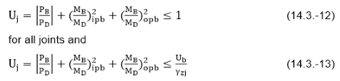
for all joints except those identified as non-critical
where
Uj - joint utilization;
PB - axial force in the brace member from factored actions;
MB - bending moment in the brace member from factored actions;
PD - design value of the joint axial strength (see 14.3.2);
MD - design value of the joint bending moment strength (see 14.3.2);
ipb - in-plane bending;
opb - out-of-plane bending;
Ub - brace utilization. Can be set manually to critical joints. Default value is
Υzj - extra partial resistance factor. Can be set manually to critical joints. Default value is 1.17;
Overlapping joints
The strength of joints that have in-plane overlap involving two or more braces may be determined using the requirements for simple joints defined in 14.3, with the following exceptions and additions.
a) Shearing of the brace parallel to the chord face is a potential failure mode and shall be checked.
b) Section 14.3.5 (can calculations) does not apply to overlapping joints.
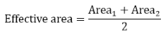
Shear capacity = fy * effective area /√3 - 1.05)
Effective area is the total area of two braces that overlap:
Area1 = 2 * p1* t1 - area of the through brace; Area2 = 2*(p2-q) * t2 - area of the overlapping brace;
where
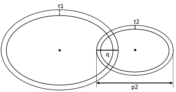
t1 - thickness of the through brace;
t2 - thickness of the overlapping brace;
p1 = d1/sin(θ1);
p2 = d2/sin(θ2);
d1, d1 - original diameter of the through and overlapping braces respectively;
θ1, θ2 - inclination of the through and overlapping braces respectively to the chord;
q - overlapping distance (negative gap);
Applied shear force is taken as summation of forces, perpendicular to the chord of the through and the overlapping braces;
Shear UC (Ultimate Capacity) is calculated as the relation of Applied shear force to shear capacity:
Shear UC = Applied shear force / Shear capacity
c) If axial forces in the overlapping and through braces have the same sign (both in compression or both in tension), the check of the intersection strength of the through brace on the chord shall use the combined axial force representing the force in the through brace plus the portion of the overlapping brace force(s). The portion of the overlapping brace force may be calculated from the ratio of the cross-sectional area of the brace that bears onto the through brace to the full area of the overlapping brace.
Modified axial force= Pd1+Pd2 * ov;
where
Pd1 - the axial force of the through brace perpendicular to the chord.
Pd2 - the axial force of the overlapping brace perpendicular to the chord.
ov - overlapping percentage,
ov=q/p*100%;
Modified axial UC= Modified axial force / Puj;
Puj - joint axial capacity from formula (14.3-1);
d) For both in-plane or out-of-plane moments, the combined moments on the overlapping and through braces shall be used to check the intersection strength of the through brace on the chord. This combined moment shall account for the sign of the moments.
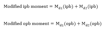
Md1, Md2 - respective in-plane and out-of-plane bending moments of the through and overlapping brace;
Modified moment UC= (Modified ipb moment / Muj(ipb))2+Modified opb moment / Muj (opb)
Modified axial and moment UC=Modified axial UC+Modified moment UC
e) The overlap onto the through brace shall be checked by using the through brace as the chord in the equations in 14.3. The through brace strength shall also be checked for combined axial force and bending moment in the overlapping brace in accordance with 14.3.6 using the value of Qf calculated for the through brace.
Note:
- Through brace is taken as a chord and overlapping brace is calculated once again with TY=100% classification to obtain axial, bending and combined UFs;
- Through brace is recalculated once again using the overlapping brace element;
- If a brace is overlapping/through at the same time for few braces – absolute maximum value is taken into account;
f) Where nominal thicknesses of the overlapping and through braces differ by more than 10 %, the thicker brace shall be the through brace
Note: through brace is a brace with a maximum diameter, or maximum thickness if equal or minimum angle if equal.
Particular cases
Sometimes models cannot represent real situations. For such cases calculations are updated to get the worst possible result according to parameters:
Case1:
Sometimes models cannot represent real situations. For such cases calculations are updated to get the worst possible result according to parameters:
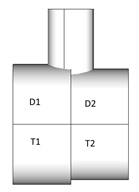
When Chord is formed by elements with different properties around the joint node and D1<>D2, D = min(D1, D2); T = min(T1, T2) are considered for calculations.
Case 2:
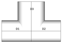
D1=D2, D1<D3. For such case, D3 is recognized as a chord as it has bigger diameter. Naturally, pipe of bigger diameter cannot be welded to smaller. Such connections are recommended to be checked.
Case 3:
a)
D1 = D2 = D3 = D4;
T1 = T2 = T3; T4 >T4;
When all diameters of connection are equal, thicknesses are compared. Element with thickness = T4 is recognized as chord.
b) In case when:
D1 = D2 = D3 = D4;
T1 = T2 = T3 = T4;
When all elements of connection are of the same dimensions, chord is recognized as pair of elements that form straight line. If any pair that matches conditions is found, random element will be recognized as chord.