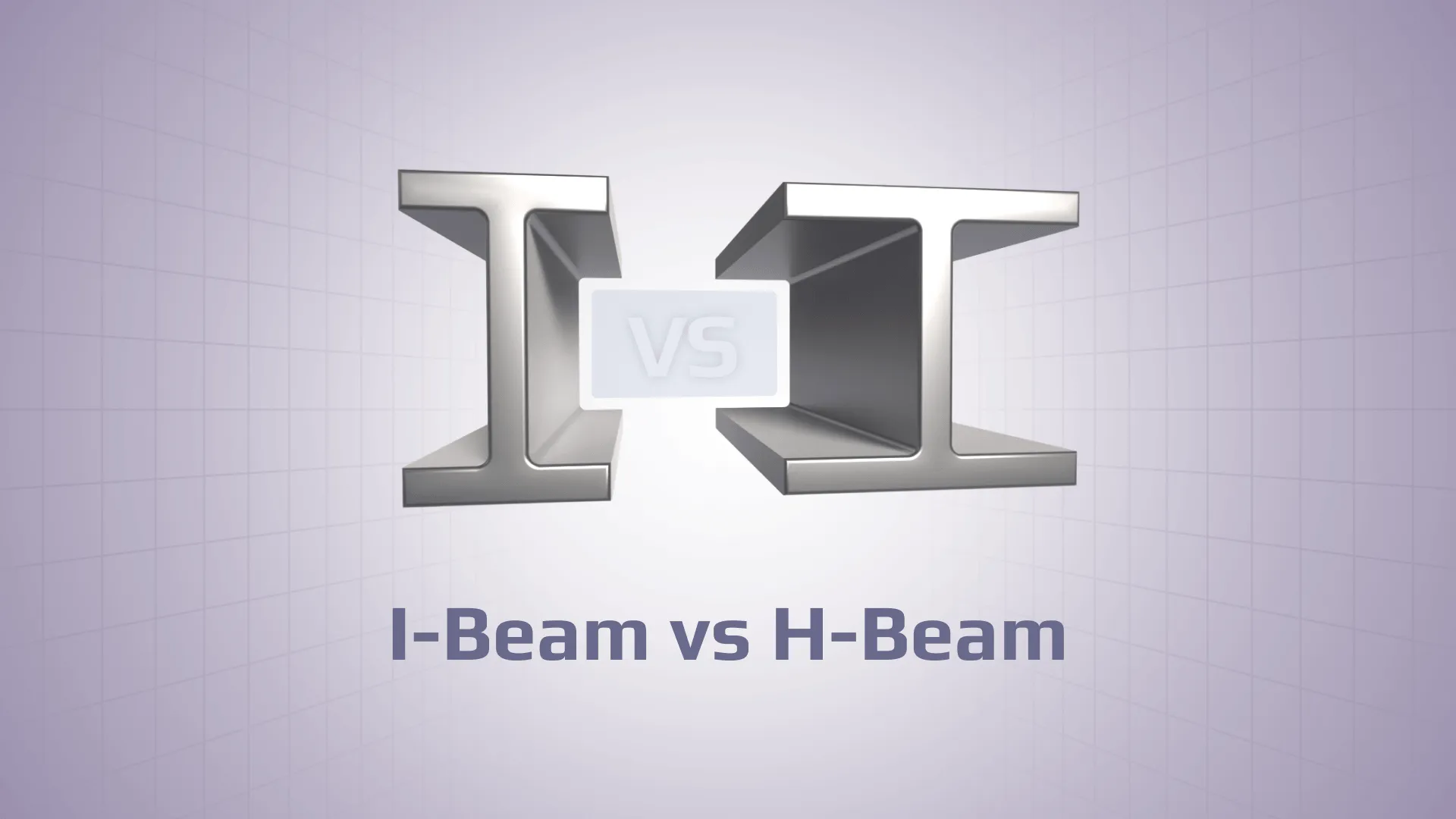
Most H-beam vs I-beam comparisons stop at shape: H-beams are wider and heavier, while I-beams are narrower and lighter. That is useful for quick recognition, but it is not enough for structural design.
In real structural design, the choice between an H-beam and an I-beam depends on much more than appearance alone. Engineers evaluate section properties, steel grade, span length, load direction, support conditions, lateral restraint, buckling resistance, connection details, fabrication requirements, and the design code being applied. In many cases, two sections with similar shapes can behave very differently once these parameters are considered.
I-Beam vs H-Beam: Quick Comparison
Factor
I-beam
H-beam / wide-flange beam
Why it matters
Shape
Taller, narrower profile
Wider flange profile, often closer to “H” shape
Affects bending, weak-axis stiffness, and connection layout
Flanges
Usually narrower; may be tapered depending on standard/profile
Usually wider and more parallel
Wider flanges can improve weak-axis behavior and connection space
Web
Often thinner relative to depth
Often thicker, depending on profile
Web thickness affects shear, bearing, and local buckling
Weight
Often lighter for comparable depth
Often heavier for comparable depth
More steel is not always better if weight or cost matters
Strong-axis bending
Efficient when depth is large
Weak axis is stronger; can be used for colums where loading is expected from both directions
Compare section modulus, not just visual shape
Weak-axis stiffness
Usually lower
Usually higher because of wider flanges
Important for columns, bracing, and lateral stability
Typical use
Beams, rafters, floor members, lighter frames
Columns, long spans, heavy frames, piles, highly loaded members
Use depends on member role, not name alone
Engineering check
Must be verified for bending, shear, deflection, buckling, connections, fatigue
Same
Code verification decides acceptability
Best-fit design question
Is strong-axis bending efficiency the main requirement?
Do weak-axis stiffness, axial load, or connection layout matter?
Helps frame the selection around structural behavior rather than shape
The practical rule: do not choose based on “I” or “H.” Choose based on section properties and verification results.
First, the Naming Is Not Universal
Engineers rarely select sections based on the “I” or “H” label alone because design decisions are driven by standardized profiles and their verified structural properties.
“I-beam” and “H-beam” are visual names, not always exact engineering designations
In practice, “I-beam” and “H-beam” are informal, geometry-based descriptions rather than strict engineering classifications. They are useful for quick communication, but structural design is not performed using these generic labels.
Engineers and designers typically work with standardized section families defined by national and international steel standards. These systems do not rely on the “I” or “H” naming convention, but instead classify members based on precise geometry and section properties required for design verification.
Depending on the region and governing standard, you will encounter different naming systems:
United States (AISC): W-shapes, S-shapes, HP-shapes
This distinction matters because real structural design is not based on whether a section “looks like an I or an H,” but on whether a specific standardized profile satisfies all required limit states under the governing code.
What Is an I-Beam?
An I-beam is a steel structural section with two horizontal flanges connected by a vertical web, forming a profile that resembles the letter “I.” It is commonly used in construction because it provides efficient bending resistance while maintaining relatively low weight.
Where I-beams are commonly used
I-beams are commonly used in structural systems where bending in one primary direction is the governing action. Typical applications include:
building beams and floor systems
roof members and rafters
secondary framing elements
platforms, walkways, and support structures
crane, machinery, and industrial frames, namely structures, mostly loaded in 1 direction
What Is an H-Beam?
An H-beam usually refers to a wide-flange steel section in which the flange width is relatively large compared to the section depth. This gives the profile a shape that visually resembles the letter “H” more closely than a narrow I-shaped section. In practical engineering language, “H-beam” is often used as a general term for wide-flange sections, including European HE profiles and similar rolled or welded shapes. But, in practice, the exact designation should always be taken from the section table or standard.
Unlike informal naming, this term does not correspond to a single standardized profile family. Instead, it typically describes a class of sections with broader flanges and more balanced geometry, which influences stiffness and load distribution behavior in structural applications.
Where H-beams are commonly used
H-beams are commonly applied in structural systems where axial load, weak-axis stiffness, connection layout, or lateral stability are critical, especially in multi-directional loading conditions. Typical uses include:
columns and heavily loaded vertical members
long-span beams
bridge and industrial structures
pile foundations / HP-type members
heavy equipment frames and support structures
members where weak-axis stiffness, flange width, or connection space is important
if wide flange is required for ease of connection or support for slabs/joints
An H-beam is often selected when the design requires higher stiffness, larger connection surfaces, improved weak-axis behavior, or greater load resistance for a given application. Its suitability must still be verified against the actual load case, boundary conditions, and governing code requirements.
H-Beam vs I-Beam Strength
There is no universal answer to whether an H-beam or an I-beam is “stronger.” It depends on the following criteria:
section size and geometry
steel grade
span length and support conditions
load type and direction
lateral restraint conditions
effective buckling length
governing limit state (bending, shear, compression, deflection, fatigue, or connection resistance)
Without these parameters, any direct strength comparison is structurally meaningless.
Strong-axis bending
In strong-axis bending, the primary parameters governing performance are the second moment of area (I) and the section modulus (W) about the major axis. A deeper section often improves strong-axis bending efficiency because more material is placed further from the neutral axis, but the exact result must be checked from section properties.
The second moment of area describes how far the material is distributed from the neutral axis, which governs stiffness and deflection, while the section modulus relates more directly to bending stress capacity.
Between I- and H-sections, both can be highly efficient in strong-axis bending if the depth is comparable. The actual performance depends on the specific profile dimensions rather than the naming convention.
Shear and web resistance
Shear forces are mainly carried by the web rather than the flanges. As a result, web geometry and thickness become critical near supports, under point loads, or in regions with high reaction forces.
A thicker or less slender web increases resistance to shear failure, web bearing, and web crippling. In heavily loaded regions, shear or local web instability can govern the design before bending capacity is reached, particularly in short-span beams or members with concentrated loads.
Compression and buckling
For columns and beam-columns, the governing failure mode is often not material yielding but global buckling.
Even if the cross-section has sufficient axial capacity, instability can occur when compressive forces cause lateral deflection and loss of equilibrium. The effective slenderness ratio, boundary conditions, and end restraints strongly influence this behavior.
This is why sections that appear “stronger” in simple bending comparisons may not perform better in compression-dominated systems.
Lateral-torsional buckling
Beams subjected to bending can fail through lateral-torsional buckling (LTB), where the member deflects laterally and twists simultaneously under compression flange instability.
This mode is especially critical when the compression flange is not continuously restrained. The resistance depends on unbraced length, torsional stiffness, flange geometry, and lateral support conditions, rather than purely on cross-sectional area or depth.
As a result, two visually similar beams can have significantly different real bending capacities depending on restraint conditions.
Deflection and serviceability
A beam may satisfy ultimate strength requirements but still fail serviceability criteria due to excessive deflection or vibration.
Serviceability ( deflection, vibration, alignment, equipment tolerances, cladding/interface limits) is governed by stiffness rather than ultimate strength, meaning that even “strong” sections may be unsuitable if they are too flexible for the required performance limits.
In Eurocode 3 beam member checks include cross-section resistance, member stability, buckling behavior, and interaction checks depending on the section class and loading conditions. In practice, this means evaluating the section class and applying the relevant Eurocode 3 checks for supported section classes, determining reduction factors for buckling curves, and checking interaction between bending, shear, and axial forces under realistic loading and support conditions.
This is the type of structured verification that SDC Verifier is built to support: checking members against code requirements using FEA results, section data, boundary conditions, and defined verification parameters. SDC Verifier helps automate Eurocode 3 member verification by applying code-based checks using section properties, material data, effective lengths, and boundary conditions defined in the model.
Why Beam Selection Cannot Stop at Shape
The key limitation of simple “I-beam vs H-beam” reasoning is that geometric similarity does not guarantee structural adequacy. A section that appears suitable in catalogue comparisons may still fail under real design conditions due to:
combined axial force and bending
lateral-torsional buckling
local web or flange buckling
excessive deflection
weld or bolt limitations
load combinations
fatigue effects
connection stiffness assumptions
boundary conditions in the FEA model
These factors often govern real design safety margins and cannot be captured by shape-based classification alone.
SDC Verifier becomes relevant. Its steel frame verification process automatically identifies structural members such as beams, columns, braces, joints, and connections directly from the FEA model and uses their geometry, orientation, effective lengths, and boundary conditions for code-based checks.
Where I-Beams and H-Beams Are Used in Construction
In practical structural engineering, the choice between an I-beam and an H-beam is not determined by shape alone, but by how the member participates in the load path, what limit states govern the design, and how well standard sections satisfy both strength and serviceability requirements under the relevant steel design code.
When an I-beam is usually a good fit
An I-beam is typically appropriate when the structural behavior is dominated by efficient strong-axis bending and when simplicity and economy are key design drivers:
The member mainly works in strong-axis bending.
Weight efficiency matters.
The span and load are moderate.
The compression flange is properly restrained.
Connection demands are not unusually heavy.
Standard rolled sections are available and economical.
Deflection and buckling checks pass with margin.
In these conditions, the section performs efficiently without requiring enhanced weak-axis stiffness or increased flange width, making it a common choice in conventional floor and roof systems.
When an H-beam is usually a good fit
H-beams or wide-flange sections are often preferred for more demanding structural roles where stability, axial force interaction, or connection geometry becomes critical. This includes heavily loaded frames, columns, long-span primary members, and systems where both bending and axial forces are significant.
They are also frequently used in industrial structures where loading is not purely vertical or static, but includes lateral actions, dynamic effects, thermal effects, or equipment-induced forces. In such cases, weak-axis stiffness, torsional stability, and connection capacity become governing factors rather than pure bending efficiency.
Where the choice becomes less obvious
Typical examples include:
building columns
offshore frames
lifting structures
machinery support frames
shipyard structures
conveyor galleries and transfer towers
seismic or wind-sensitive frames
In these applications, the governing failure mode is often not obvious at the conceptual stage, and multiple limit states may interact, making section selection dependent on detailed analysis rather than preliminary assumptions.
Example: Why Two Similar Beams Can Give Different Verification Results
Two steel sections may appear very similar in overall size yet behave quite differently during structural verification. A narrow I-section and a wide-flange or H-type section with approximately the same depth can produce different utilization ratios depending on the governing limit state, restraint conditions, and load combination.
Check
Why results may differ
Strong-axis bending
Depends on section modulus around the major axis
Weak-axis bending
Wider flanges usually improve weak-axis stiffness
Shear
Web thickness and shear area matter
Lateral-torsional buckling
Compression flange restraint, torsional properties, and unbraced length matter
Compression buckling
Radius of gyration and buckling length affect capacity
Connections
Wider flanges may simplify bolt/weld layout
Weight
Higher resistance may come with higher self-weight and cost
Even when two members satisfy the same bending requirement, one section may fail serviceability, or stability checks earlier than the other. For example, a deeper narrow section may be highly efficient in strong-axis bending but more sensitive to lateral-torsional buckling or weak-axis instability. A wider H-type section may improve stability and connection behavior but increase weight and fabrication cost.
Image: I-beam and H-beam
Where:
bf = flange width
h = section depth
tw = web thickness
tf = flange thickness
How to Choose Between an I-Beam and H-Beam
Selecting between an I-beam and an H-beam is an engineering verification problem, not a visual preference. The correct section is the one that satisfies all governing code checks with acceptable weight, fabrication complexity, and safety margin under the actual loading and support conditions.
Step 1: Define the member role
Possible member roles include:
beam
column
brace
beam-column
support frame
pile
girder
Step 2: Identify governing loads
Typical actions include:
bending moments
shear forces
axial tension or compression
torsion
fatigue loading
dynamic effects
thermal loads
Step 3: Check section properties
Important parameters include:
cross-sectional area
second moment of area
section modulus
plastic modulus
radius of gyration
shear area
Step 4: Check stability
Depending on the structural configuration, verification may require checks for:
project-specific rules and classification requirements
Step 7: Optimize
SDC Verifier allows engineers to perform beam section optimization to reduce steel weight while still maintaining compliance with Eurocode 3, AISC, ISO, and other standards. This is particularly relevant for structures such as cranes, offshore modules, towers, bridges, and industrial frames where stability and serviceability checks often govern before material yielding.
Common Mistakes When Comparing I-Beams and H-Beams
Simplified comparisons between I-beams and H-beams often ignore the factors that actually govern structural performance. These assumptions can lead to incorrect section selection and unexpected verification failures.
Mistake 1: Assuming H-beams are always stronger
H-beams are often wider and heavier than narrow I-sections, but that does not automatically make them stronger. Strength depends on the specific section geometry, steel grade, loading conditions, and the governing limit state. Beams are heavier, so self load increases.
Mistake 2: Comparing only depth
Two beams with similar depth can have significantly different flange widths, web thicknesses, cross-sectional areas, and stiffness properties. Similar overall dimensions do not guarantee similar structural behavior.
Mistake 3: Ignoring lateral restraint
A beam may have sufficient bending resistance on paper but still be limited by lateral-torsional buckling. The restraint conditions of the compression flange can significantly change the available capacity.
Mistake 4: Ignoring connection design
The member itself may satisfy code requirements while the connection becomes the governing issue. Welds, bolts, end plates, stiffeners, and load introduction regions can control the final design.
Mistake 5: Choosing by table capacity without checking the full structure
Section tables provide useful preliminary information, but real structures include boundary conditions, load combinations, eccentricities, second-order effects, and fabrication details. Final selection should always be based on complete structural verification.
Mistake 6: Ignoring availability and fabrication constraints
Engineers do not select sections based on theory alone. Stock availability, supplier catalogues, welding and fabrication limitations, transport constraints, and connection detailing requirements can all determine the final feasible option, even if a section performs well in calculations.
I-Beam vs H-Beam: Summary
I-beams are often efficient for strong-axis bending and lighter structural members. H-beams or wide-flange sections are often better where higher stiffness, heavier loads, column behavior, or connection space matters. But the final choice should be based on section properties and code verification, not the visual shape alone.
For preliminary selection, shape gives a useful clue. For final selection, utilization checks decide, and in SDC Verifier, it is the utilization results under real load combinations and limit states that ultimately confirm whether the section is adequate.
FAQ
What is the main difference between an I-beam and an H-beam?
The main difference is geometry. I-beams are usually deeper and narrower, while H-beams or wide-flange beams have wider flanges. This affects stiffness, strength, buckling behavior, weight, and connection design.
Can two beams with similar size have different verification results?
Yes, because section modulus, weak-axis stiffness, web slenderness, restraint conditions, connection layout, and governing code checks can differ.
Is an H-beam stronger than an I-beam?
Not always. An H-beam is often heavier and may provide higher stiffness or capacity in some applications, but strength depends on section size, steel grade, span, load direction, restraints, and code checks.
Which is better for columns, I-beam or H-beam?
H-beams or wide-flange sections are often preferred for columns because wider flanges can improve weak-axis behavior and connection layout. But the final decision depends on axial load, buckling length, end restraints, and the design standard.
Which is better for beams?
I-beams can be efficient for strong-axis bending. H-beams can be better for heavier loads, longer spans, or cases where lateral stability and connection space are important.
Are H-beams and wide-flange beams the same?
Often the terms overlap in casual use, but they are not always exact synonyms. Engineers should refer to the actual section designation, such as IPE, HEA, HEB, UB, UC, W-shape, S-shape, or HP-shape.
Why does beam verification matter after selecting the section?
Because a beam can fail by bending, shear, compression buckling, lateral-torsional buckling, local buckling, fatigue, weld failure, bolt failure, or excessive deflection. Shape alone does not prove compliance.