What Is Mesh in Finite Element Analysis (FEA)?

In Finite Element Analysis (FEA), mesh plays a crucial role in transforming real-world structures into a numerical model that can be analyzed. It consists of small, interconnected elements and nodes that break down complex geometries, enabling engineers to predict how a structure will respond to various physical conditions. This article will explain what a mesh is, how it is created, and why its quality directly impacts the accuracy of FEA simulations.
The Basics of Meshing: Elements and Nodes
Mesh in FEA bridges between a real-world problem and its numerical solution, allowing engineers to analyze complex geometries and predict behavior under various conditions. Namely, it works alongside the solver, boundary conditions, and material properties to bridge this gap. By discretizing a continuous domain into smaller, manageable elements connected by nodes, the mesh transforms the problem into a format solvable by computational algorithms.
A mesh consists of two primary components: elements and nodes.

(source)
- Elements: These are smaller subdomains, known as finite elements, collectively approximate the geometry of the analyzed structure. Each element represents a relatively small portion of the structural details or the object, ensuring higher accuracy in capturing the behavior and achieving correct results. Elements can take various shapes, including triangles, quadrilaterals, tetrahedrons, and hexahedrons, depending on the dimensionality and complexity of the problem.
Depending on the nature and dimensionality of the problem, finite elements can be categorized into 1D, 2D, and 3D types.
- 1D elements are typically used for modeling slender structures like beams, trusses, or frames.
- 2D elements represent surfaces or planar structures, such as plates and shells.
- 3D elements are used to model solid structures with volume, capturing the full complexity of three-dimensional behavior.
The elements’ type and size significantly affect the simulation’s accuracy and computational cost.
- Nodes are the points elements connect and where primary calculations, specifically displacements, are performed. The deformation of the model is determined solely through the displacement of these nodes. Based on the calculated displacements, the solver computes derived quantities such as stresses and strains for the finite elements. This sequential process highlights the central role of nodal displacements in the overall analysis.
The interaction between the elements is done only through the nodes, which allows the solver to compute results across the entire domain. The solver utilizes a process called discretization to transform the initial system of differential equations into a system of algebraic equations, replacing differential operators with finite differences.
The entire computational domain is divided into a finite number of subdomains, known as finite elements. The equations defined at each node within these elements are solved simultaneously, considering principles such as equilibrium, compatibility, and material behavior, to produce the simulation results.
Meshing in FEA: Preparing the Model for Accurate Analysis
The primary idea of meshing is to enable the accurate numerical representation of a physical domain for analysis. Since real-world structures are continuous and often irregular, directly solving them mathematically is impractical and often impossible. Meshing simplifies this by:
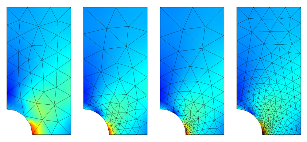
- Breaking Down Complexity: Complex geometries can be accurately represented and considered by dividing them into smaller, simpler shapes (elements), making the calculations manageable.
(source)
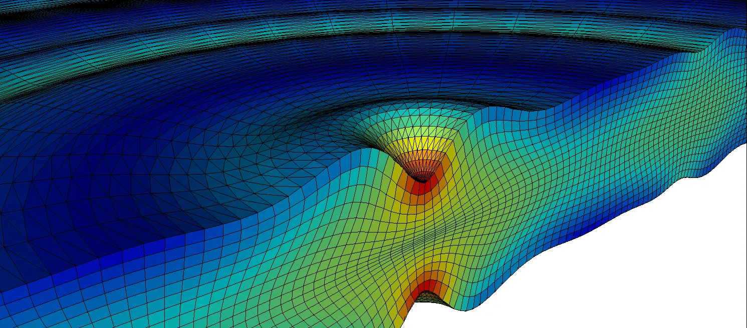
- Capturing Local Effects: Meshing ensures finer resolution and greater accuracy in critical areas by using smaller elements in regions of high stress or strain gradients.
(source)
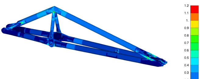
- Balancing Accuracy and Efficiency: Adaptive meshing techniques can optimize the trade-off between computational cost and result precision by refining the mesh only where necessary.
How Meshing Enables Structural Simulations
Meshing is integral to the FEA process as it directly impacts the quality and reliability of the simulation. The process typically involves the following steps:
- Geometry Preprocessing: Geometry is prepared for meshing, removing unnecessary details that may complicate the analysis.
- Material Definition: Materials are defined for the model, specifying their properties (e.g., elasticity, thermal conductivity) to accurately represent how the system will behave under various conditions.
- Property Definition: The properties of the finite elements, including element type, shape, and dimensions, are defined. These properties ensure that the mesh can accurately simulate the real-world system.
- Mesh Generation: The domain is discretized into elements and nodes. Tools often provide automatic or manual mesh control options, allowing engineers to refine areas of interest.
- Loads and Boundary Conditions: Once the mesh is generated, loads (e.g., forces, pressures) and boundary conditions (e.g., constraints, fixed supports) are applied to the model. These inputs define how the system will interact with external factors during the analysis.
- Solver Application: With the mesh in place, the solver applies numerical methods, such as the finite element method, to approximate the system’s behavior under defined loads, boundary conditions, and material properties.
- Result Interpretation: Post-processing tools display results like stress, deformation, or thermal gradients, giving engineers insights into the system’s performance.
Modern structural analysis software, such as SDC Verifier, allows the creation of mesh nodes and elements automatically and manually.
The automatic mesh generation is based on the model’s geometry which defines the boundary region within which the mesh will be created. In contrast, manual meshing allows more control over the process, enabling engineers to refine specific areas as needed.
Advanced Aspects of Meshing
While the basics of meshing lay the groundwork for effective analysis, advanced techniques can further enhance simulation quality and efficiency:
- Adaptive Meshing: This involves refining the mesh dynamically during the simulation, focusing on areas where greater accuracy is needed. For instance, regions with steep stress gradients or intricate geometry features may benefit from finer meshes.
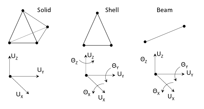
- Element Types: Depending on the problem, element types, such as solid, shell, or beam elements, may be chosen to best represent the physical characteristics of the structure:
- Solid Elements (3D):
Used for 3D stress states and complex geometries.
Provide detailed stress distribution throughout a volume.
- Shell Elements (2D):
It is ideal for thin-walled structures like plates or shells.
Capture bending and membrane behavior efficiently.
- Beam Elements (1D):
Suited for slender members like beams and trusses.
Handle axial, bending, and torsional behavior.
(source)
- Mesh Metrics: Tools to evaluate mesh quality, such as aspect ratio, skewness, and warpage, help engineers ensure that the generated mesh will produce reliable results.
Moreover, SDC Verifier offers a comprehensive meshing toolbox with advanced features to enhance the accuracy and efficiency of FEA modeling:
- Mapped Meshing: Ensures structured, uniform meshes ideal for regular geometries, improving accuracy and reducing solver time.
- Geometry-Mesh Editor: Tools like a washer and pad allow precise mesh adjustments in critical areas, such as around holes or stress concentration points.
- Mesh Editor: This tool enables the splitting and editing of local elements to refine the mesh in specific regions, ensuring better resolution in high-stress zones.
- Adaptive Meshing: Automatically refines the mesh during simulation based on stress gradients or other criteria.
- Mesh Quality Checks: Built-in tools evaluate mesh metrics like aspect ratio, skewness, and warpage, ensuring reliable results.
Common Challenges in Meshing
Despite its importance, meshing presents several challenges that engineers must address:
- Geometric Complexity: Highly detailed geometries can lead to excessively dense meshes, which increase computational costs. This can also result in numerical issues like ill-conditioning and excessive memory usage. For example, tiny holes, fillets, and roundings in a model may require outstanding elements to capture their details, which could lead to poor element quality or excessive mesh density. Additionally, accuracy may not improve if the solver’s numerical precision cannot handle such fine elements. Simplifying geometry where possible is often necessary.
- Element Distortion: Poor-quality elements, such as those with extreme aspect ratios or angles, can lead to numerical inaccuracies or solver convergence issues.
- Mesh Convergence Studies: For reliable results, it is essential to ensure that the solution remains stable and accurate as the mesh is refined.
- Free Edges: Unmerged nodes or elements at boundaries can result in disconnected areas, leading to unexpected solver behavior.
- Coincident Nodes or Elements: Overlapping nodes or elements can create inaccuracies, requiring careful checks during preprocessing.
- Connecting Different Element Types: Properly linking beam-to-solid, beam-to-plate, or plate-to-solid elements ensures accurate representation of interactions between structural components.
Meshing Software and Automation
Modern FEA software often includes powerful meshing tools to streamline the process. Features like automatic meshing, guided refinement, and pre-built templates simplify the task for engineers.
Discover how SDC Verifier facilitates the generation of 2D meshes from 3D geometry, streamlining the process by automatically extracting key surfaces and optimizing mesh resolution for efficient analysis while preserving the critical structural details:
Automation in meshing reduces human error and speeds up the process, but engineers must still validate the generated mesh to ensure it meets the requirements of the specific analysis.
Best Practices for Meshing
To achieve reliable results, engineers must adhere to several best practices:
- Choose the Right Element Type: Based on model behavior, desired results accuracy, and model size, select the appropriate element type. The choice of element affects the analysis’s precision and the computational cost due to the number of elements.
- Ensure Proper Element Quality: Avoid skewed or excessively distorted elements and triangular and tetra elements in the critical areas, as they can lead to inaccurate results.
- Use Refinement Judiciously: Focus higher-resolution meshes in areas of interest, such as sharp corners or high-stress zones, while maintaining coarser meshes elsewhere to save computational resources.
- Mesh Convergence Study: Run multiple simulations with varying mesh densities and monitor key results, such as stresses or displacements, to ensure they stabilize as the mesh density increases. This confirms that the results are not overly sensitive to the mesh size and that the mesh has sufficiently resolved the model without introducing unnecessary computational overhead.
- Account for Symmetry: When applicable, leverage symmetry in the geometry to reduce the size of the mesh and computational requirements.
- Simplify Geometry Where Possible: Reduce the complexity of the geometry to minimize the model size and computational effort while ensuring the analysis’s results remain reasonable and accurate for the analysis.
Conclusion
A well-constructed mesh ensures better precision, stability, and efficiency in calculations, while a poorly generated mesh can lead to errors and misleading outcomes. By understanding how meshing works, selecting the right element types, and refining the mesh where needed, engineers can significantly improve their analysis quality. Mastering meshing techniques is key to making informed design decisions and optimizing structural performance in real-world applications.
