A global FEA model may satisfy global checks, but that does not always prove local fatigue-sensitive details are adequately verified.
As offshore wind structures operate under millions of load cycles from wind, waves, and gravity, the most critical structural issues often develop locally rather than globally. A model may satisfy global strength requirements while still overlooking stress concentrations, complex load transfer, or fatigue-prone details that influence long-term structural integrity.
This article compares a global beam model with a detailed plate model for wind turbine support structures, showing how global and detailed FEA complement each other, how environmental loads are incorporated, and how structural-item verification helps engineers make more confident design, assessment, and inspection decisions.
Why Acceptable Global Results Can Still Leave Local Risk Unresolved
Wind turbine support structures are designed to operate for 20-30 years while transferring aerodynamic and environmental loads safely into their foundations. Throughout their service life, they are continuously exposed to changing wind, waves, currents, gravity, and turbine-induced loads. Although these structures are assessed for fatigue using standards such as DNV-RP-C203, and verified using advanced simulation methods, structural problems can still develop over time.
In many cases, the issue is not insufficient global strength. It is the slow development of fatigue damage in local structural details exposed to millions of cycles.
One reason is that a finite element model simplifies the reality. Engineers must make assumptions about geometry, material properties, loading, and boundary conditions to create a computationally manageable model. However, actual operating conditions continue to change throughout the structure’s lifetime. Wind varies with height/direction/weather; separately, material/weld/support assumptions can change over time.
As these factors accumulate, the behavior of the real structure can differ from the assumptions made during design.
Finally, the issue lies in the level of modelling detail. If critical connections, welds, or other structural features are simplified or omitted, a model may satisfy global verification requirements while failing to represent the local behavior that governs fatigue-sensitive regions. It means that acceptable global results alone do not automatically demonstrate local structural adequacy.
This article is based on SDC Verifier’s webinar “Simulating Hidden Structural Risks in Wind Turbines Support Structures”. Follow the link to see more details:
What A Global Beam Model Can Reliably Tell You
For preliminary design and global verification, global beam models provide an efficient representation of a wind turbine support structure. They are quick to build, computationally inexpensive, and allow engineers to evaluate the overall structural response before investing time in detailed modelling.
A global beam model can be used to:
Understand the overall structural behavior and deformation.
Evaluate load paths and force distribution throughout the structure.
Identify regions with high utilization that may require further investigation.
Perform preliminary member screening early in the design process.
Obtain engineering insight with relatively low computational effort.
Beam models are useful for global response and screening, not for local weld stress, plate/stiffener behavior, or detailed connection geometry.
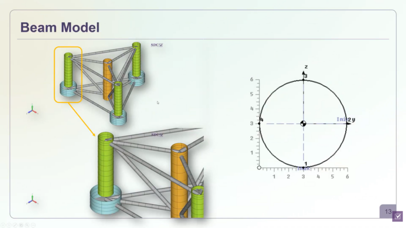
In the model below, the beam representation contained only around 300 elements, making it fast to prepare and analyze. Even with this simplified approach, the analysis highlighted several regions where the utilization factor exceeded the allowable limit. These locations provided valuable guidance on where a more detailed investigation could be justified.
Image: Comparison of beam model and plate model
Rather than serving as the final proof of structural adequacy, a global beam model is an effective screening tool. It helps engineers understand how the structure behaves as a whole and identify the locations that deserve more detailed local verification before moving to higher-fidelity models.
Where Simplified Models Stop: Joints, Welds, Plates, Stiffeners, and Load Transfer
In a typical beam model, members are connected through common nodes, making it less practical to represent the actual geometry of welded connections, stiffeners, and plate assemblies.
A detailed plate model makes it possible to represent features that are either simplified or omitted in a beam model, including:
Connection geometry between structural members.
Plate and stiffener arrangements inside tubular sections.
Welded details that govern local stress distribution.
Local stiffness variations that influence how loads are transferred through the structure.
In the example below, the detailed model contained approximately 600,000 finite elements and explicitly included stiffeners and welded connections. This level of detail enabled the verification model to represent local geometry, stiffness, and stress distribution more explicitly, providing the information required for evaluating local stress distribution and fatigue-sensitive regions.
Images: Simplified beam model vs. detailed plate model
The comparison between the beam and plate models also illustrates an important modelling strategy. The simplified model identified the general areas where utilization was highest, while the detailed model provided the level of representation needed to investigate those locations further. The purpose of refinement is therefore not to replace global analysis, but to examine critical regions where local geometry and load transfer may influence the verification outcome.
A Practical Escalation Path: Global Screening → Local Detailed Verification
A detailed model is not the starting point for every project. Instead, an efficient verification workflow begins with a global representation of the structure and introduces additional modelling detail only where it provides engineering value.
A practical workflow can be summarized as follows:
Build a global beam model to evaluate overall structural behavior, deformation, load paths, and preliminary utilization.
Review the analysis results to identify regions where utilization exceeds the acceptance criteria or where connections deserve closer investigation.
Refine only the critical areas by creating a detailed plate model that includes local geometry, stiffeners, and welded connections.
Perform structural verification on the refined model using the applicable design standards and recognized structural items such as welds, panels, beam members, and joints.
This staged approach helps balance computational efficiency with verification quality. A simplified model provides a fast way to understand how the structure behaves as a whole, while a detailed model focuses computational effort on locations where local geometry and stress distribution become important for verification.
Applying Wind, Wave, and Buoyancy Loads to Wind Support Structures
The quality of structural verification depends not only on the FE model itself but also on how accurately the loading environment is represented. For offshore wind turbine support structures, environmental loads do not act independently—they occur simultaneously, change over time, and influence the structural response together.
Typical loading conditions include:
Wind loads, acting on both the turbine and the support structure.
Buoyancy and hydrostatic pressure below the waterline.
Ocean current loads acting on submerged structural members.
Image: Wave and buoyancy setup
These loads are highly variable. Wind velocity changes with height and direction, while wave conditions, water pressure, and current loads continuously vary throughout operation. As a result, engineers typically evaluate multiple load cases and load combinations to ensure different operating scenarios are represented in the verification process. Because these loads are cyclic in nature, they also play a significant role in fatigue assessment.
Image: Height-dependent wind-load setup and pressure preview
For wind loading, pressure can be defined as a function of height above the ground or waterline and applied in different directions and angles. The pressure distribution can then be reviewed before analysis to confirm that the loading corresponds to the intended design scenario.
For offshore structures, buoyancy and wave loading require additional environmental parameters, including the waterline location. If the waterline is known, it can be defined directly. Alternatively, it can be estimated based on the balance between the structure’s weight and the surrounding water. Wave loading can then be characterized using parameters such as wave height, wavelength, direction, and phase to represent different environmental conditions.
From FE Results to Structural Items: Beams, Panels, Joints, And Welds
Finite element results alone are not sufficient for structural code verification. Engineering standards evaluate structural items, such as beam members, welded connections, plate panels, and joints, rather than individual finite elements. Before these checks can be performed, the corresponding structural items must first be identified within the FE model.
SDC Verifier allows you to automate this process through the following structural recognition tools:
Weld Finder – automatically detects welded connections throughout the model (where the model is prepared with the required property/intersection definition), identifies weld geometry and dimensions, and distinguishes between welded regions, non-welded regions, and weld intersections when required by the selected design standard. The tool also establishes local weld coordinate systems, so stresses are evaluated in the correct directions for fatigue assessment.
Panel Finder – recognizes plate panels for plate buckling verification and automatically extracts parameters such as panel length, width, thickness, and other properties required by the selected standard.
Beam Member Finder – identifies beam members throughout the structure and determines the member properties required for beam verification, including buckling lengths in different directions.
Joint Finder – detects beam connections and classifies them according to their geometry, including one-dimensional, two-dimensional, and three-dimensional joints. These recognized joints can then be used for joint verification according to the applicable design standard.
Image: Weld, panel, beam, and joint recognition views in SDC Verifier tools
The recognized structural items remain fully editable. Engineers can modify recognized welds, split or merge panels, adjust recognition parameters, or add missing structural items without rebuilding the finite element model.
Fatigue And Buckling Checks for the Critical Locations
Once structural items have been recognized, they can be verified according to the requirements of the selected design standard. Rather than evaluating individual finite elements, fatigue, buckling, and member checks can be performed on the recognized welds, beam members, panels, and joints.
For offshore wind turbine support structures, the demonstrated workflow applies to DNV-RP-C203 for fatigue assessment. During the setup, engineers define parameters required by the standard, including:
In the following comparison, the global beam model identified the general connection regions where utilization exceeded the acceptance criterion. The detailed plate model then provided a more explicit representation of those same locations, making it possible to evaluate local stress distribution, welded details, and fatigue-sensitive areas in greater detail. The comparison illustrates how detailed verification complements global analysis.
Images: Beam-model and plate-model utilization result comparison
The DNV-RP-C203 fatigue analysis shown here is based on representative load cases and assigned cycle counts.
Using Local Verification Results to Prioritize Inspection or Design Changes
Once verification has been completed, the results can support decisions such as:
prioritizing inspection of fatigue-sensitive structural details;
identifying components that require closer monitoring;
evaluating whether local design modifications should be considered;
documenting verification results for future maintenance and reassessment.
You can transfer these results to SDC SAM, a web-based structural asset management platform. Instead of navigating through large FEA reports, engineers can review the condition of an asset through a structured hierarchy; from the complete support structure down to individual components, sections, and recognized structural items.
How SDC Verifier Supports the Workflow
An efficient verification workflow combines global structural assessment with targeted local analysis rather than relying on a single model for every engineering decision. SDC Verifier supports this approach by bringing the entire verification process into one environment, from model preparation to code compliance and reporting.
Within a single software, SDC Verifier, you can:
prepare and mesh the FE model in SDC Verifier or work with results from Ansys/Simcenter/Femap in the connected FEA environment;
define wind, wave, buoyancy, and other loading conditions;
create load combinations;
recognize structural items such as welds, beam members, panels, and joints;
perform fatigue, buckling, strength, bolt, and joint verification according to the selected design standards;
generate comprehensive engineering reports.
SDC Verifier currently supports more than 60 engineering standards, covering fatigue, static strength, beam buckling, plate buckling, bolts, welds, and joints. Engineers can also review the equations used during verification and trace how individual utilization values are calculated for specific structural items.
Apart from standalone version, SDC Verifier also provides extensions for Ansys Mechanical and Simcenter 3D/Femap, allowing recognized structural items and code-based checks to be performed directly on analysis results from those platforms.
Rather than replacing global analysis, SDC Verifier extends it with the tools needed for targeted local verification. So, you can start with an efficient global screening model, refine only the regions that warrant closer investigation, and perform code-compliant verification where local structural behavior governs the final assessment.