Column buckling checks are crucial for structural engineering, ensuring stability under compressive loads. Buckling — a lateral deflection that can lead to structural failure — occurs when compressive forces exceed a column’s critical load capacity.
What is Column buckling
Buckling occurs in columns when a compressive load is applied to a column that exceeds the column’s critical load. The critical load is the maximum load a column can carry before it loses stability and begins to buckle or bend. This can happen due to various factors, such as column size, material, and the type of loading applied to the column. The critical load is influenced by the column’s slenderness ratio and length ratio to its least gyration radius. Columns with a high slenderness ratio are more likely to buckle than those with a low slenderness ratio.
The mathematics of buckling was first explored by Leonard Euler and is presented in the following formula:
\[P_{cr}=\frac{\pi^{2}EI}{L^{2}}\]where E is the modulus of elasticity in (force/length2), I is the moment of inertia (length4), L is the length of the column.
Long columns can be analyzed with the Euler column formula
\[F=n\pi^{2}EI/L^{2}\]where
- F = allowable load (lb, N)
- n = factor accounting for the end conditions
- E = modulus of elasticity (lb/in2, Pa (N/m2))
- L = length of column (in, m)
- I = Moment of inertia (in4, m4)
The formula helps to understand how the critical load is affected by column length, cross-sectional properties, and material properties, choose appropriate materials for columns based on their modulus of elasticity and other relevant properties, perform preliminary stability checks, optimize column designs to use materials and resources efficiently while meeting safety requirements.
Columns transfer loads vertically while beams transfer loads horizontally into columns, and they often coexist in a structure. Learn more about the essentials of beam buckling in detail in this video:
Slenderness Ratio and Its Impact on Buckling
The slenderness ratio is a non-dimensional parameter that describes how slender a column is by comparing its length to its cross-sectional properties. The slenderness ratio is defined as:

Where:
- L is the effective length of the column,
- r is the radius of gyration.
Columns with a high slenderness ratio (long, thin columns) are considered slender and are more likely to buckle under lower loads. In contrast, columns with a low slenderness ratio (short, thick columns) can sustain higher loads before experiencing buckling. This relationship is expressed in Euler’s formula, which reveals that a column’s load-carrying capacity before buckling decreases significantly as its length increases.
For example, if a column’s length doubles from 2 meters to 4 meters, its critical buckling load reduces to approximately one-quarter of the original value. This illustrates how even slight increases in slenderness can sharply reduce a column’s stability under compressive loads.
To better understand the stress implications, we can calculate the critical buckling stress by dividing the critical buckling load by the column’s cross-sectional area:
\[\sigma_{cr} = \frac{\pi^2 E}{\left(\frac{L}{r}\right)^2}\]where ( E ) is the Young’s modulus of the material. This formula highlights that slender columns experience lower critical buckling stress, making them more susceptible to buckling at lower loads. In contrast, stocky columns with lower slenderness ratios can withstand much greater stresses.
In practical applications, understanding a column’s slenderness ratio helps engineers assess whether buckling or material failure (e.g., crushing) is the primary risk under compressive loads, informing material selection and design to ensure structural safety and efficiency.
Critical Buckling Stress vs. Slenderness Ratio
For slender columns, the critical buckling stress is low due to their high slenderness ratio. In contrast, stocky columns with lower slenderness ratios can handle much greater stresses. When the slenderness ratio is very low, the material’s yield strength is reached before buckling occurs, leading to failure by crushing instead of buckling. This creates two distinct failure modes:
- Stocky columns fail due to crushing when the compressive stress exceeds the material’s yield strength.
- Slender columns fail by elastic buckling under lower stress levels.
For columns in between these two extremes, buckling behavior is more complex. In this transition region, failure is a mix of both plastic and elastic modes, a phenomenon known as inelastic buckling. To accurately model inelastic buckling, methods such as Engesser’s theory or Shanley’s theory are typically used, as Euler’s formula is insufficient for these cases.
Many industry design codes include buckling curves that account for the transition from elastic to inelastic buckling, providing engineers with the necessary guidelines to safely design columns under compression.
Elastic Buckling
Elastic buckling is a significant concern for slender columns, as it represents a sudden loss of stability when subjected to compressive loads. This phenomenon can be compared to the way a spaghetti noodle snaps under bending pressure. Interestingly, elastic buckling occurs at stress levels that are lower than the material’s ultimate strength, highlighting the inherent instability of the column itself, which leads to its failure.
To minimize the risk of buckling, the ideal column design should feature a uniform cross-section and maintain initial straightness. However, in real-world applications, structural components often exhibit minor imperfections due to manufacturing processes and variations in material properties. These imperfections can act as initiating factors for buckling, exacerbating the problem.
Additionally, buckling can be triggered by eccentric loads, where the force applied to the column is not perfectly centered along its axis. This misalignment introduces extra bending moments, further increasing the likelihood of buckling and necessitating careful consideration in design to ensure structural integrity.
Types of Column buckling
The different types of column buckling are primarily categorized based on the boundary conditions and buckling modes. Here are the main types of column buckling:
Types of Column Buckling
| Buckling Type | End Conditions | Buckling Mode | Critical Load Formula | Significance |
|---|---|---|---|---|
| Euler Buckling (Pinned-Pinned) | Both ends pinned | Single half-wave | \( P_{cr} = \frac{\pi^2 E I}{L^2} \) | Common in simple structural designs; allows rotation at both ends, leading to straightforward deflection. |
| Fixed-Fixed Column | Both ends fixed | Two half-waves | \( P_{cr} = \frac{4 \pi^2 E I}{L^2} \) | Higher load-bearing capacity due to both ends being constrained, making it less prone to buckling under moderate loads. |
| Pinned-Free Column | One end pinned, other end free | Quarter-wave | \( P_{cr} = \frac{\pi^2 E I}{4L^2} \) | Least resistance to buckling; useful for studying extreme deflection but not for practical load-bearing applications. |
| Fixed-Pinned Column | One end fixed, other end pinned | Three-quarters of a wave | \( P_{cr} = \frac{2.046 \pi^2 E I}{L^2} \) | Moderate resistance to deflection, suitable for frames and structures requiring intermediate buckling resistance. |
| Fixed-Fixed with Intermediate Support | Both ends fixed, with lateral support along length | Intermediate lateral-torsional | No standard formula (requires specialized analysis) | Additional lateral support improves stability; ideal for long columns requiring reinforcement, such as in bridges and towers. |
| Column with Eccentric Loading | Axial load applied off-center | Flexural-torsional buckling | No standard formula (requires combined load analysis) | Common in real-world applications with slight misalignments or asymmetrical loads; design must account for bending and buckling. |
| Non-Uniform Columns | Varying cross-section along length | Complex buckling patterns | No standard formula (requires custom analysis) | Used for columns with changing cross-sectional properties, such as tapered or non-uniform columns; advanced analysis needed. |
| Slender Strut Buckling | Very slender, imperfections impact | Varies with imperfections | No standard formula (accounts for material behavior) | For very slender columns, minor imperfections and material nonlinearities significantly affect buckling behavior, requiring detailed design consideration. |
Considering different column buckling types helps ensure structures’ safety, reliability, and compliance with established engineering standards. By analyzing different buckling modes, engineers can determine the critical loads at which buckling becomes a concern and design structures to resist such failures.
How to avoid Column buckling
In general, buckling can be prevented using a larger cross-section or stiffer material. Additionally, it can be seen in the critical load calculation that the buckling load is inversely proportional to the length of the structural member squared, so if required, reducing the length of the structural member or bracing the member can be used to increase the critical buckling load.
Column buckling checks with SDC Verifier case study
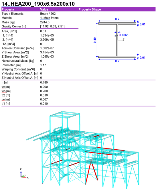
The project covers compliance of the supporting structure with such standards as API RP 2A, ISO 19902, Norsok N004, DIN 15018, and FEM 1.001. The whole steel structure and the structural element in question were checked considering gravity load, dead weight of equipment load, platform dead load, handrails and chutes dead load, platform load, conveyor load, conveyor load (only forces), wind load in X-direction-equipment, wind load in Y-direction-equipment.
With the help of Beam member finder, torsional length was obtained, and length torsional and torsional-flexular buckling were calculated.
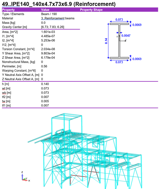
Based on the beam member check results according to Eurocode 3 standard, several beam members with utilization factor above 1 were found. All members that showed a Utilization factor above 1 and did not satisfy requirements according to Eurocode 3 standard required reinforcement.
Moreover, additional checks according to standards such as tubular joint check, deflection check, serviceability check, or Eurocode3 beam member check show how the structural elements will behave at different conditions and help engineers conclude if the columns are safe to operate or their parameters should be changed, reinforcements added, connections modified and so on to ensure the structure safety.
The automatic Model Setup Report created by SDC Verifier contains the entire model descriptions and explanations of all calculation details for the supporting structure and all its components separately. The stakeholder can easily extract the essential results from the report and repeat the structure’s analysis in the future to compare the changes in the state of the structure with time.
Column buckling checks with SDC Verifier provide a structured approach to ensuring structural stability under compressive loads. Through automated load assessments and compliance checks, SDC Verifier enables engineers to optimize column designs and meet regulatory standards efficiently.
