The Peak Finder tool finds all peak zones based on output results and presents them using a special plot and a summary table. Never miss a hot spot.
Introduction
The complex behavior of different structures forces engineers from civil engineering and many other industries to use the finite element stress analysis in their practice. Although it helps to find out the calculated resulting parameters (e.g. stresses, internal forces, displacements etc.) in details, it also has its biggest “drawbacks” in most FEA programs:
- Detailed outcomes normally require detailed modelling;
- Detailed modelling leads to the extensive post-processing of the model to find all peak stresses and estimate them
- As a consequence, it requires a lot of time to be spent on post-processing.
Fortunately, such a powerful CAE package as Ansys, Femap and Simcenter3D helps us to make the modeling part as easy / fast as possible with its user-friendly modelling tools, while the post processing part still remains a time-consuming one.
In this article we will show how to reduce the required time for post-processing significantly.
What is Peak Stress?
Most engineers use this phrase to describe many different things like:
Stress singularities
Stress singularity in many cases is an FEA convergence problem, which leads to the theoretically “infinite” stress at certain location.
It can be caused by different local features, like:
- Concentrated Point load, applied to a model;
- Boundary conditions (constrained model at a point);
- Sharp corners of finite elements etc.
It’s important to understand that this peak stress is not realistic and therefore should be treated appropriately.
Stress concentration
A lot of articles, which describe what is a “stress concentration” can be found, but in short – this is a location in your model with sudden changes, when there are irregularities in the geometry / material of a structural component, such as corners, fillets, holes etc. It causes the modified flow of stress, which locally becomes “more concentrated” from such details (for example, fillet stress concentration occurs when 2 plates with different thicknesses, which are welded together with a butt joint, are subjected to tensile force in opposite directions).
The magnitude of stress concentration calculation can be expressed as a non-dimensional stress concentration factor, computed as the ratio between the highest and nominal stresses.
Stress magnitudes with its stress components
Very often engineers use the “peak stress” phase describing the highest calculated stress level in the structure, regardless of the reasons for its occurrence. So be aware, that the peak stress is not always a stress singularity or a stress concentration, but it can also be the “standard” stress you got used to, without any “pitfalls”.
Why do we need it?
Normally, having the model being analyzed, engineers want to ensure that the maximum calculated stress level under the different load cases prescribed by the industry standards, does not exceed its allowable limits (e.g. working on Static Stress Checks or Fatigue checks, which are based on the extreme weld stresses, etc.). It is one of the key-factors which defines the structural integrity and reliability during the operational conditions, so it’s extremely important to realize that the missed peak stress in the structure can be crucial and lead to unforeseen circumstances in the real life, like structural damage / global failure in the future.
The complexity of the problem
It’s not a “super” complicated task to find all overstressed zones in FEM models that are built with beam elements (1D elements), especially because the stresses, in this case, are given per cross-section of the structural element and not in details! Although it does not take a lot of time to determine the “problematic” locations (let’s say with the stress level above Yield / Safety factor), but it makes it hard to estimate how critical the situation is in your structure.
In this example we’ve built the finite element model of the test Port crane, which consists of 1D elements. With help of SDC Verifier, we applied a lot of load combinations according to FEM 1.001 standard and executed Fatigue check for this structure (see below). Stress overshoots (fatigue damage) are represented by the Utilization factor, which should not be higher than 1 to stay within the allowable limit.
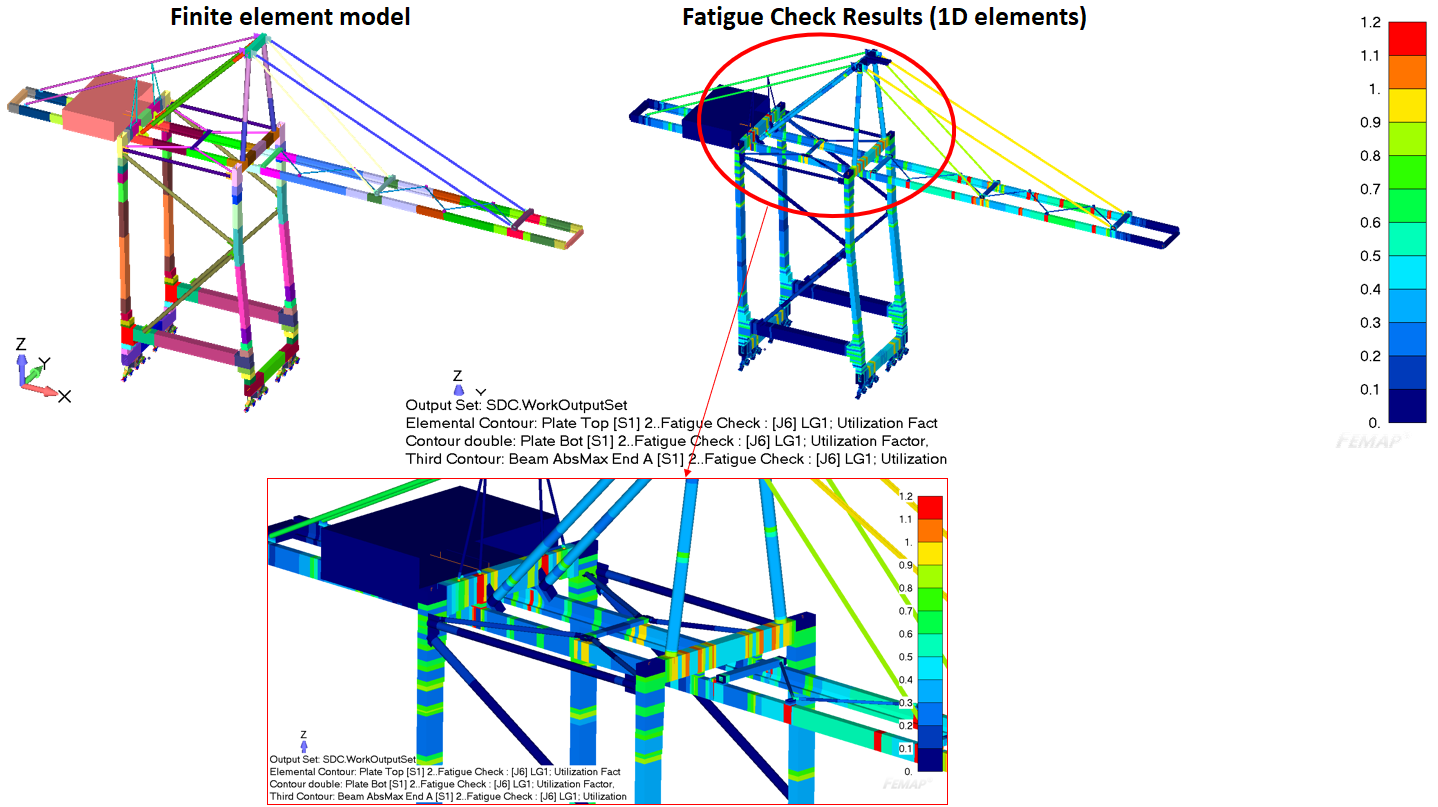
Although all “red spots” are shown per cross-section of the beams, which simplifies the task find stress overshoots, there are still a huge amount of locations to be checked.
A more detailed model, which is built with plate/shell elements (2D elements) changes the situation significantly, because now instead of relatively simplified shapes, all details at each point of the cross-section of structural members can be easily taken into account:

For large detailed models, results are shown over the surface but only the results at the visible part of the model can be checked:
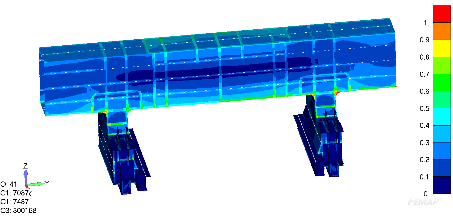
It’s quite risky because there still can be hidden locations with overstressed elements somewhere inside the structure:

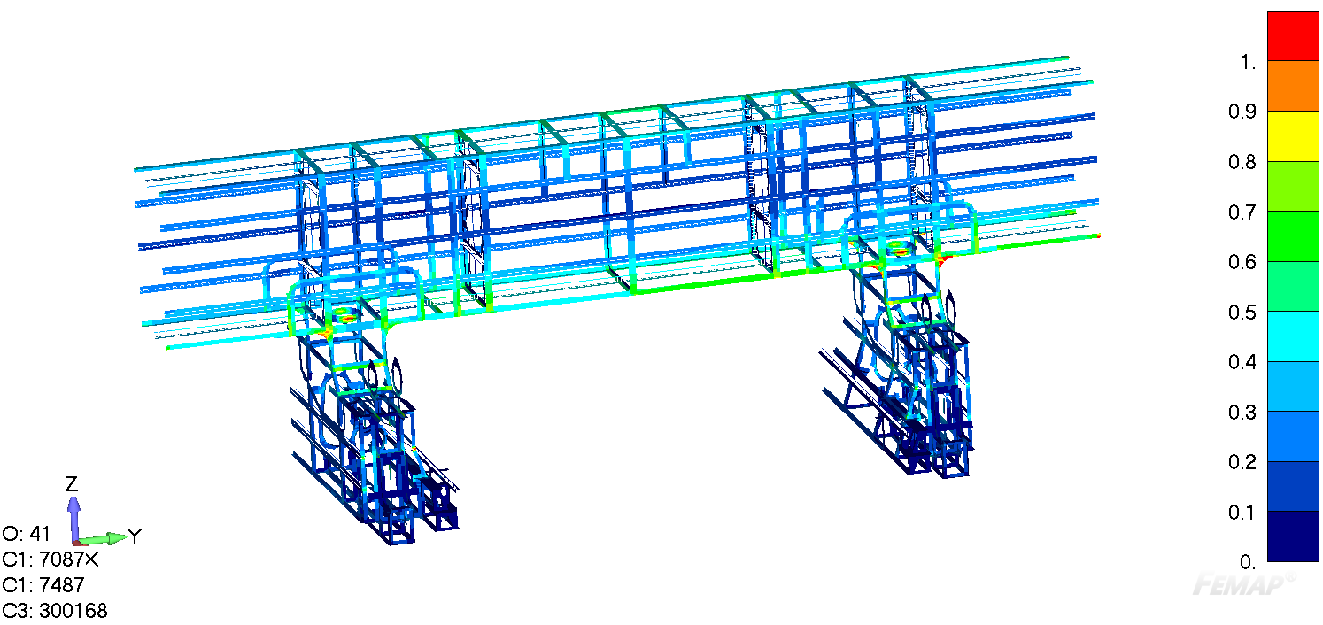
Using SDC Verifier plots with only the welds selected (from the Weld Finder tool) gives you a better picture and enables inside viewing, but results on small elements can still be easily overlooked. Furthermore, for exact maximum values hand post-processing is still required:
FEM model, which is made with solid / volume elements (3D elements) is no exception and very often becomes even more complicated task:
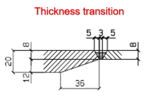
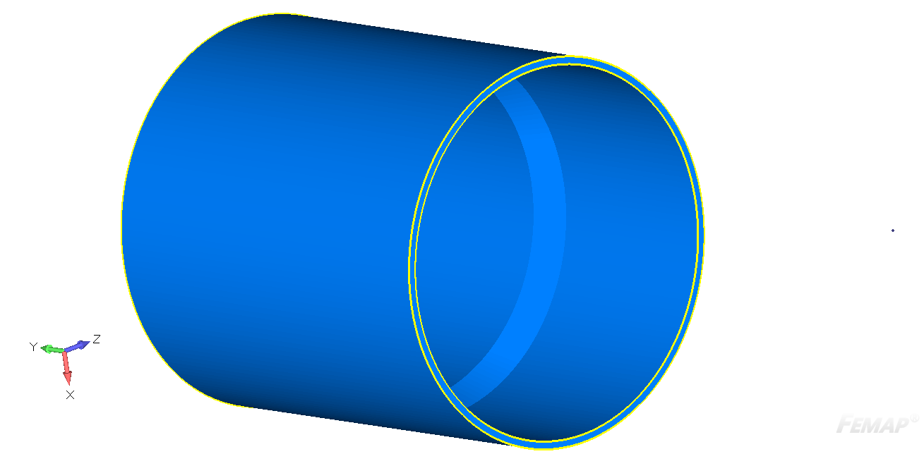
In the example below, we can see the volume finite element model of the typical tubular connection with different thickness transition:
Typical view from the outside:
Typical view from the inside:
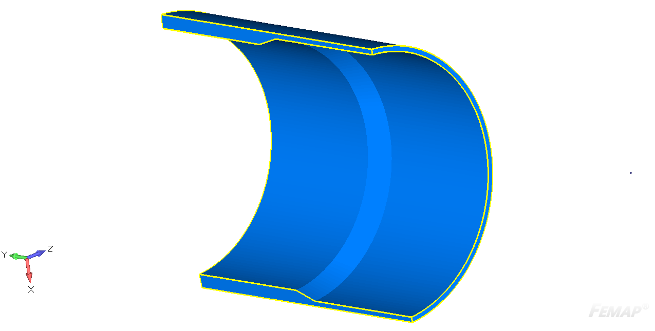
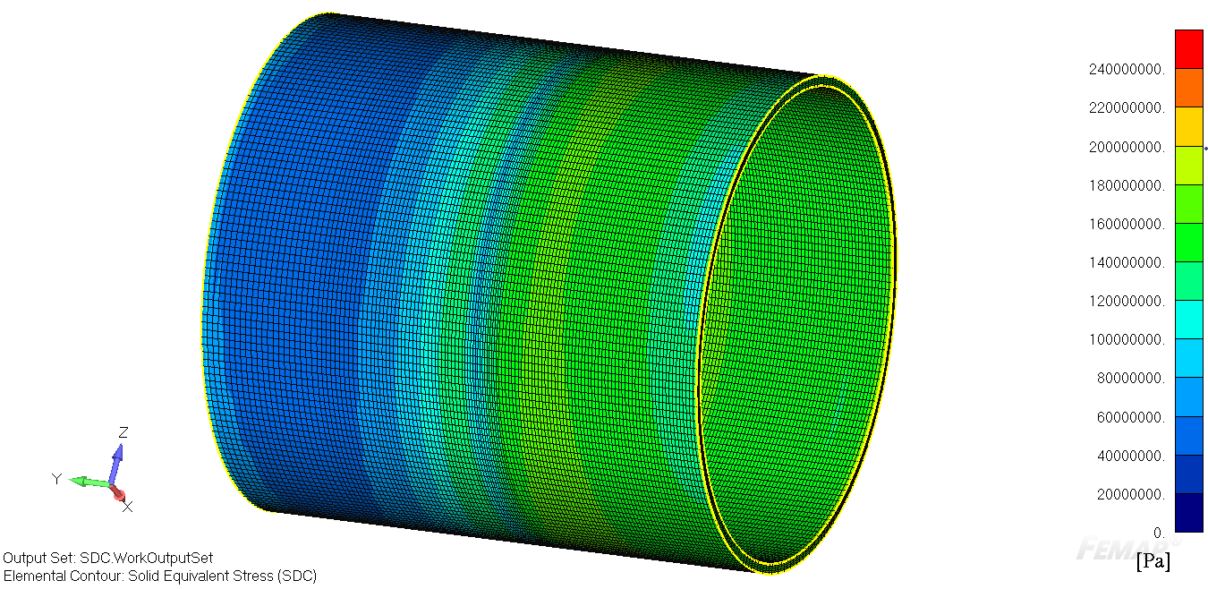
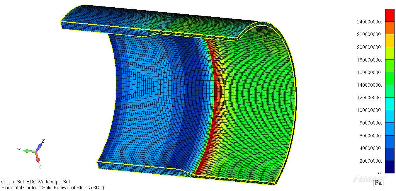
Under the loads in 2 directions transferred to this structural item, the detailed stress is received.
From the outside view it can look like there is no problem (stress level doesn’t exceed allowable):
But from the inside view it can be clearly seen that the stress level is much higher than the yield limit on the inner side at the thickness transition (exceeds allowable!). Such “tricky” locations can be easily missed without close model inspection and afterward results in cracks in the real life, which are not easy to identify.
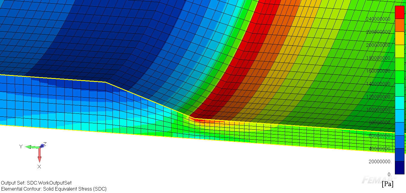
And now just imagine the complexity of finding the peak zones if your model consists of not 1 structural element modelled in details, but a few of them, or few dozens, or even hundreds.
Solution
With the help of SDC Verifier, all Peak Stresses and other types of outcomes (i.e. standard check results, strain, weld stresses, global plate stresses, line element forces etc.) can be found in seconds!
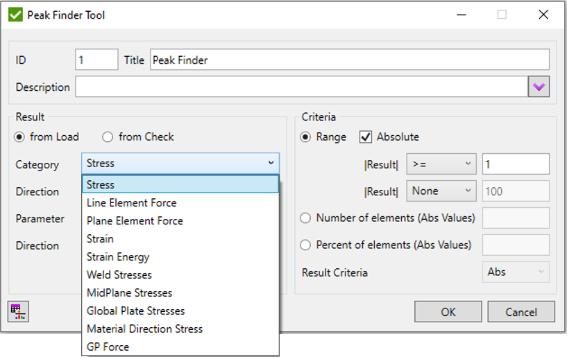
The Peak Finder tool finds all peak zones based on the output results and presents them using a special plot and a summary table. The peaks for any simple FEA results can be found (from Load), but also all available results from the SDC Verifier checks can be used as shown in the example below (from Check):
From Load
From Standard Checks
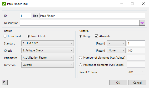
With the help of the user-friendly interface, you can set up the interested criteria of the results parameters (i.e. category, standard, check, direction parameter) and the interested values range for the outcomes (“<”, “=”, “>”, “<=”, “=>”, “None” of a certain value). Besides, it is possible to find only a certain “Percentage” of elements with the highest stress level or “Number” of the most overstressed elements as well.
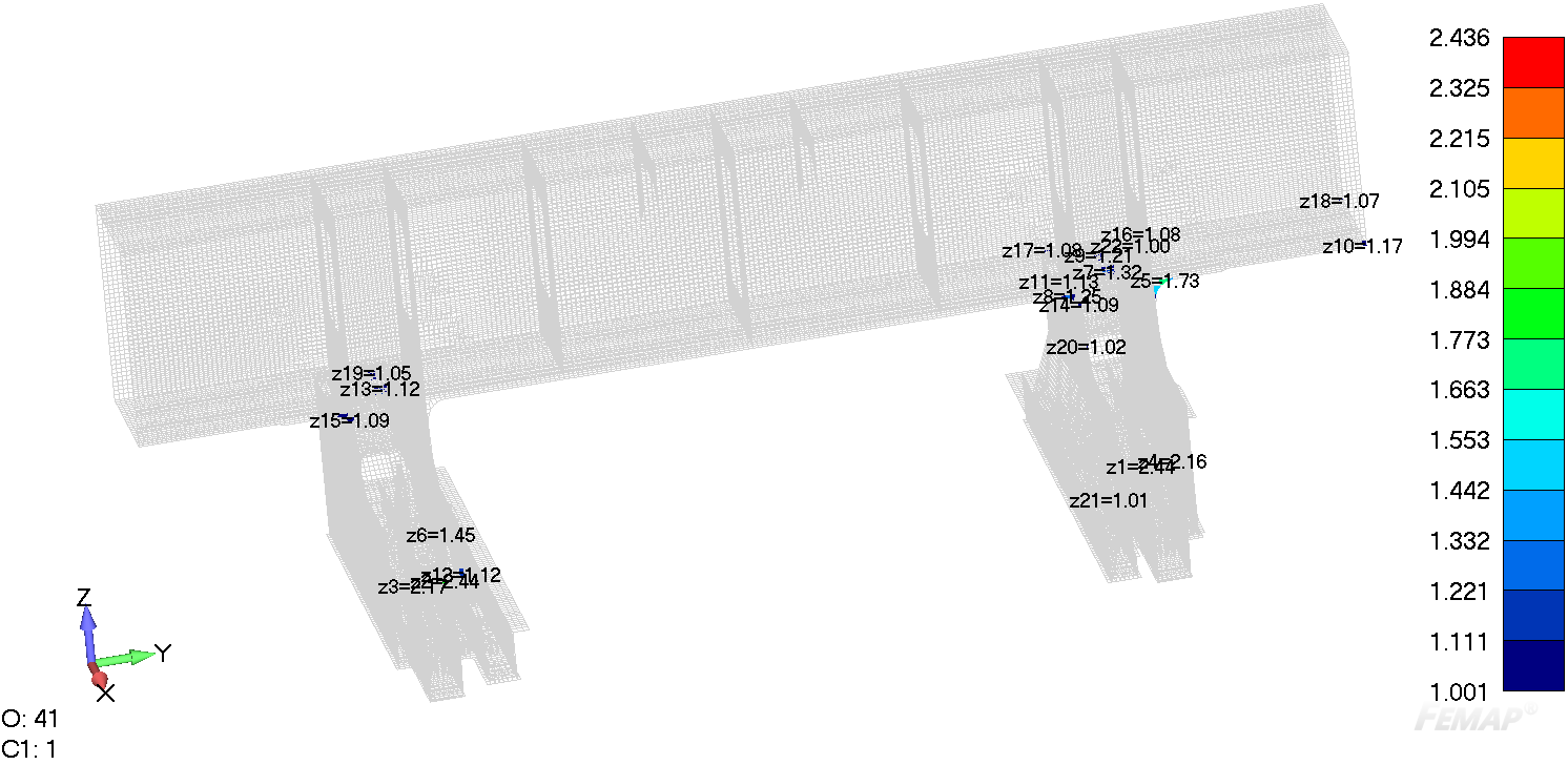
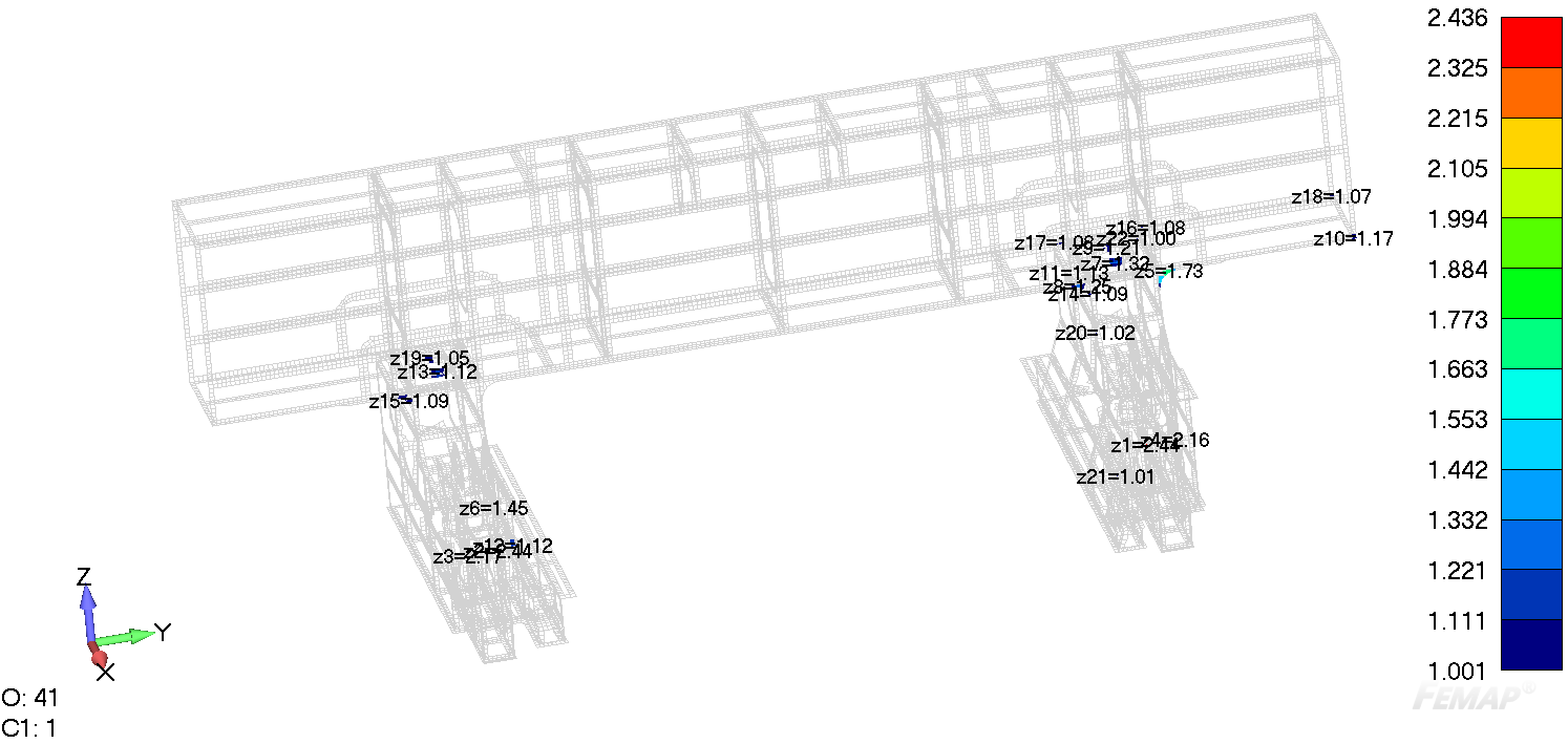
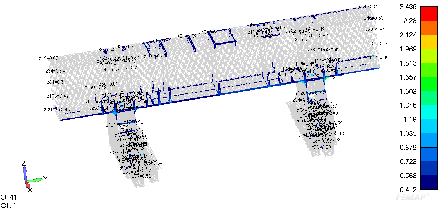
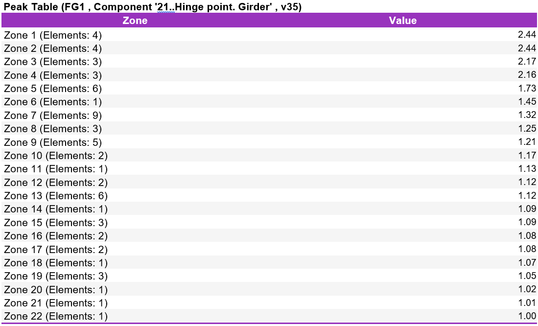
The peak values (all results above 1) of the utilization fatigue calculations are found and shown on the result plot in the separate peak zones with their unique number:
Full detailed part (UF≥1):
Welds only (UF≥1):
Full detailed part (5% of elements with the highest stress level):
Welds only (5% of elements with the highest stress level):
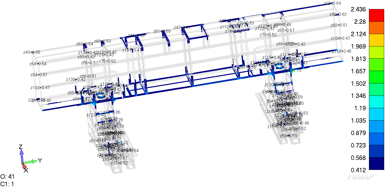
Full detailed part (50 over stressed elements):
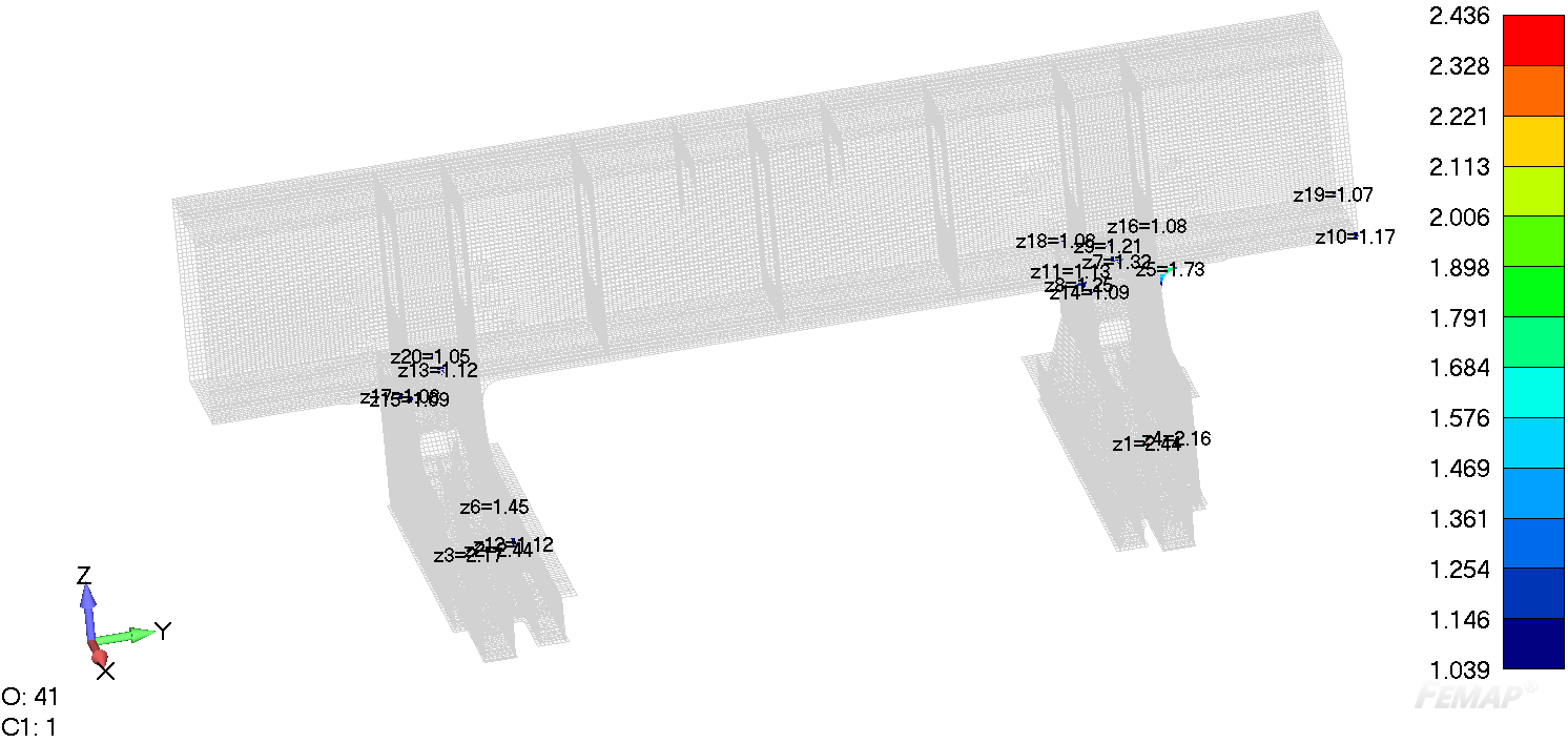
Welds only (50 overstressed elements):
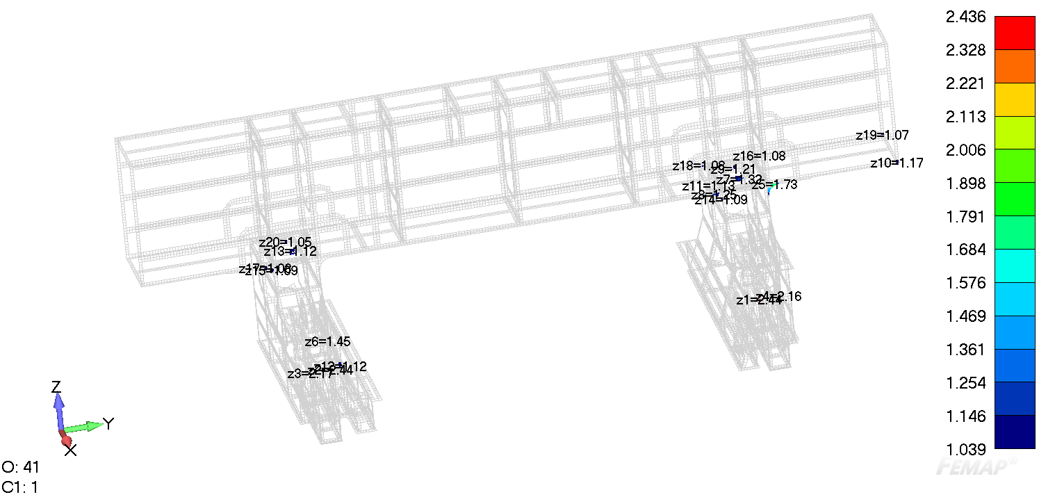
In the peak finder result table, the highest result for each zone is shown:
If necessary, the Peak values can be plotted directly as labels above the overstressed zones with/without their unique numbers:
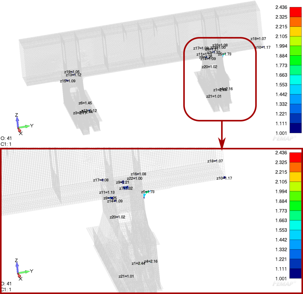
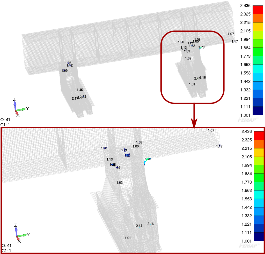
In the end, these and many other outcomes can be automatically reported with help of the FEA Report Generator and then exported in the PDF / Word / PowerPoint document if required.
Summary
With the help of the Peak Finder tool in SDC Verifier, all Peak Stresses and other types of outcomes (i.e. standard check results, strain, weld stresses, global plate stresses, line element forces etc.) can be found in seconds and automatically generated in a report, if required. The different features of the tool allow users to set up only the interested criteria for findings and avoid unnecessary outcomes. In many cases it saves hours, days and even weeks compared to the manual post-processing routine.
Note: all examples in this article are not real structures and made on purpose!
