Connection Finder
Connection Finder recognizes connections, their dimensions and is based on Joints.
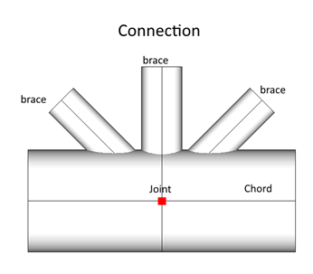
Each connection is a set of elements connected to the joint node (see Joints Finder) and consists of:
Chord – is a set of non-welded elements that form straight line;
Braces – welded to chord elements at joint node;
To start recognition execute from the ribbon:
Press to define recognition options:
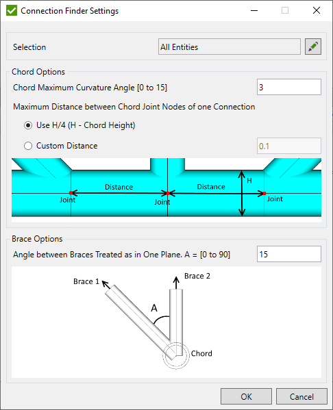
Selection – select joint nodes where recognition will be performed using Selector Control;
Chord maximum curvature angle - chord elements not always form the straight line. To include an inclination in the chord default angle of 3 degrees is used.
Maximum distance from joint nodes of one connection on the chord - include joints that are formed by multiple nodes. It is possible to set Custom distance or use the distance that equals D/4 where D - chord diameter for circular braces;
Angle between braces treated as in one plane - defines the allowable angle between braces of one connection that are located in different planes;
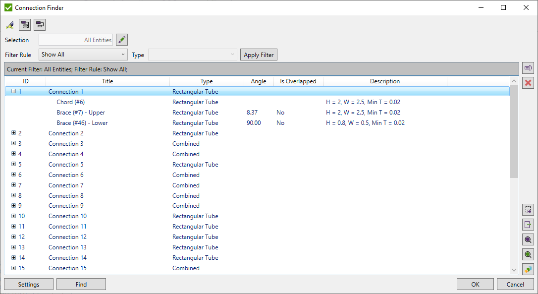
Press Find to recognize all connections of the model. The following types of connections are recognized:
-
Circular Tube - cross section of all braces and chord elements of connection is circular tube;
-
Rectangular Tube - cross section of all braces and chord elements of connection is rectangular tube;
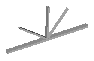
-
I-Beam - cross section of all braces and chord elements of connection is I-Beam tube;
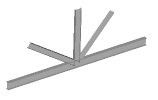
-
Combined - at least one cross section of brace or chord element is different from other cross sections;
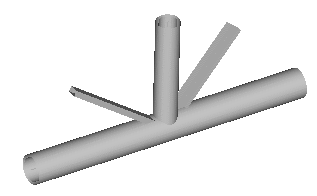
Connection details display respective type of connection, chord or brace and cross section dimensions. Brace contains only 1 element with ID defined in brackets (#) connected to the joint node. Connection can contain braces from both sides of the chord: Upper- braces from one side of chord; Lower - braces from opposite side of chord;

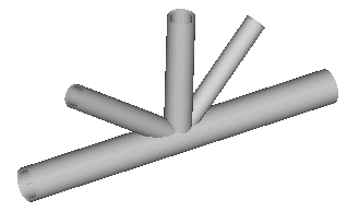
Note: Multiplane (3D) connections are split onto plane (2D) connections:
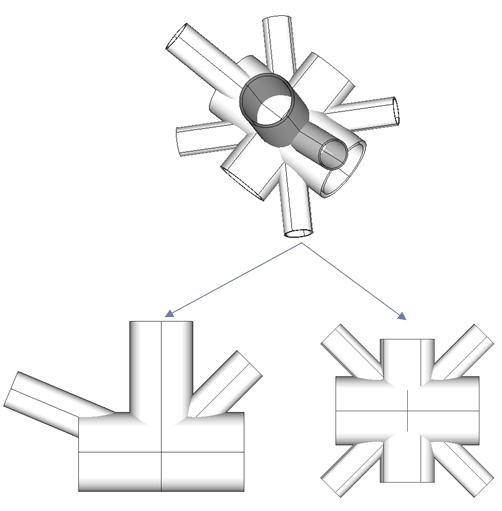
 - rename selected connection
 - select element from the model and highlight respective connection in the list that contain selected element;
 - remove selected connections;
 - export selected connections using Export Menu;
 - highlight selected connections on the model;
 - display only selected connections on the model;
Press  to automatically highlight selected connections on the model.
 - show an information about all connections;
 - hide an information about all connections;
It is possible to filter connections by Selection or by Filter Rule:

Filter Rules:
- Show All – display all connections on the defined Selection;
- Connection Type – display connections by connection type (circular only etc.);
- Show Overlapped – display connections where at least one of the brace overlaps another;
Press Apply Filter to filter connections that match the filter settings. Applied filter is displayed above the table:

