Custom Standard
Standard is a set of checks and items to perform calculations according to formulas and rules.
To add Custom Standard execute from the ribbon.
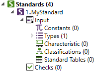
Standard contains:
It is possible to convert a predefined (built-in) standard into Custom. Select standard and execute from the Standard context menu:
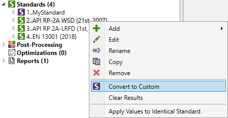
Apply Values to Identical Standard - copy all the Input (Constants, Characteristics, Classifications, Standard Tables) of the standard from selected standard to another standard of the same type. Command is available only for predefined standards.
command can be executed on individual item of the Input part of the standard or on a group of items (e.g. Characteristics).
Constants
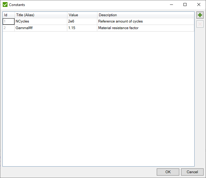
Constants is a static value which can be used in checks with the help of Alias. It is useful to create constants and use them in formulas because in case of modifications (related to constants) it is required to make a change in one place only.

Constant dialog box:
Types
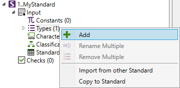
Standard type is a list of titles that can be used in classification or characteristic instead of numbers. To add a new type press from the menu:
The following dialog window will be displayed:
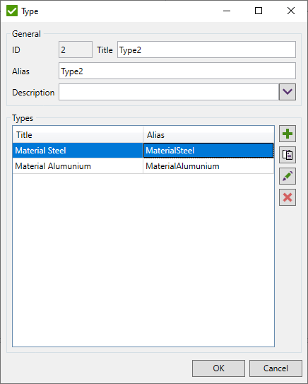
 - add a new item;
 - paste titles/aliases from the clipboard.
Spaces in alias will be removed automatically;
 - edit the selected item;
 - remove selected items;
- import already existing classification type from existing standards:
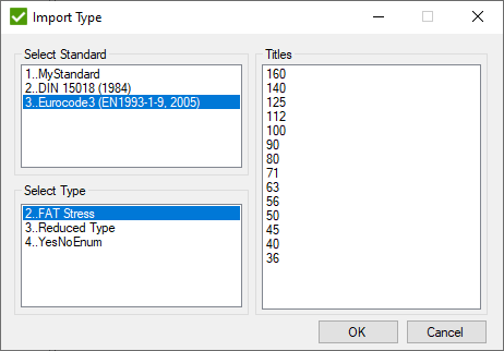
Select standard, standard type and press OK to create new standard type.
- export all types to the existing custom standards. If type already exists it will be skipped:
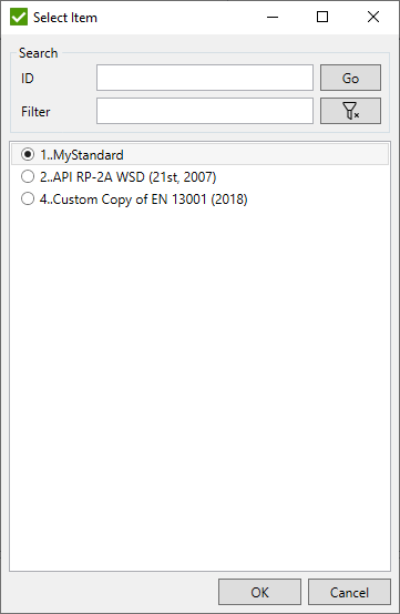
Characteristics
SDC Verifier allows adding extra properties called Characteristics to use them in Standard check formulas. There are four types of characteristics: Material, Property, Elemental and Load.
To add Characteristics use the context menu:
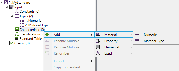
All characteristic types can be created by additional subtypes that are taken from the list. is a default type and allows to apply numeric values in characteristic.
Add Material/Property Characteristic:
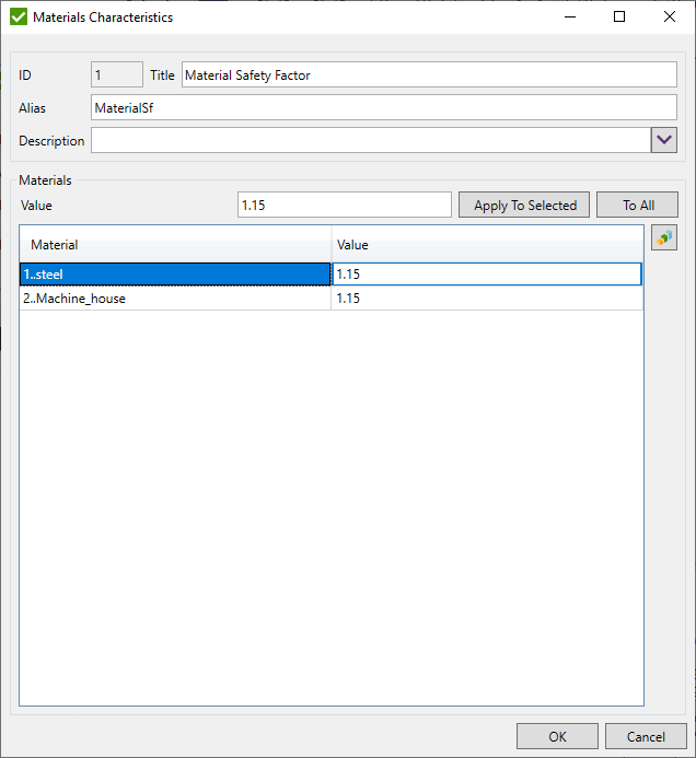
Set to use characteristic in check formulas.
To plot characteristic values for all materials/properties press  .
.
Add Element characteristic:
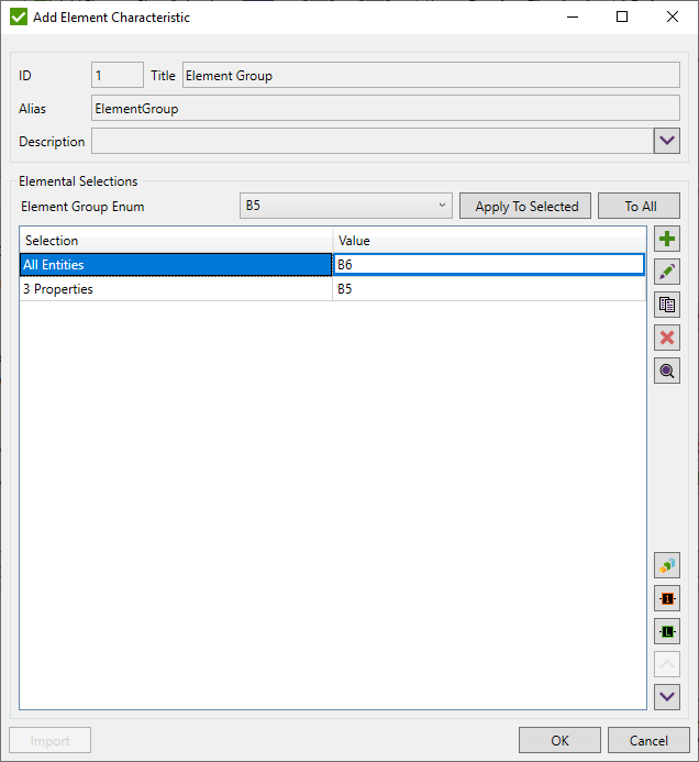
 - add Node/Element group and set the value:
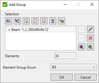
 - edit group elements and value;
 - copy selected groups with values;
 - remove selected groups;
 - highlight selected group nodes/elements on the model;
 - plot characteristic values of selected groups;
 - colored plot with selection title label of selected groups;
 - colored plot with value label of selected groups;
 - move selected conditions up;
 - move selected conditions down.
Note: is available for element type characteristic only with Numeric Type.
Press to import Beam Length/Effective Length Factor from Beam Member Finder, Plate Width/Length and Stiffener Length from Panel Finder or Welds from Weld Finder.
All previous data from characteristic can be removed:
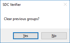
Import dialog box:
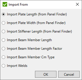
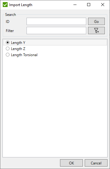
If Beam Member data is selected then it is required to select the direction from the list:
Note: For weld finders, only the groups with 0 values will be created.
Classification
Classification is an extra element characteristic that can be set over directions.
To add classification select type in classification menu item:
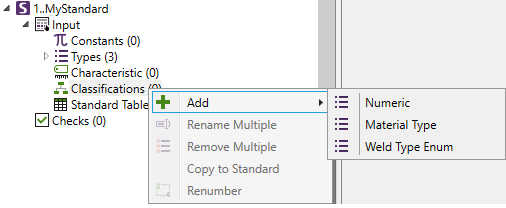
- allows to set numeric values of the classification. It is flexible as it can be used in the creation of any kind of own calculations. It is available for all types of standards. Extra classifications are possible to be created using Types. Different standards have their own predefined classifications. For example, DIN 15018 Standard predefined classifications are Element group, Weld Type and Material Type.
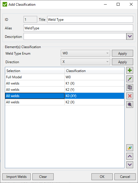
Set classification Alias to use it in Custom check formulas.
 - add classification condition;
 - edit selected condition;
 - copy selected conditions;
 - remove selected conditions;
 - move selected conditions up;
 - move selected conditions down.
Note: The first condition cannot be modified, moved, copied or removed.
 - highlight selected condition elements;
 - select direction to plot classification values as criteria plot or as label plot;
Selection - part of the model for which plot will be displayed;
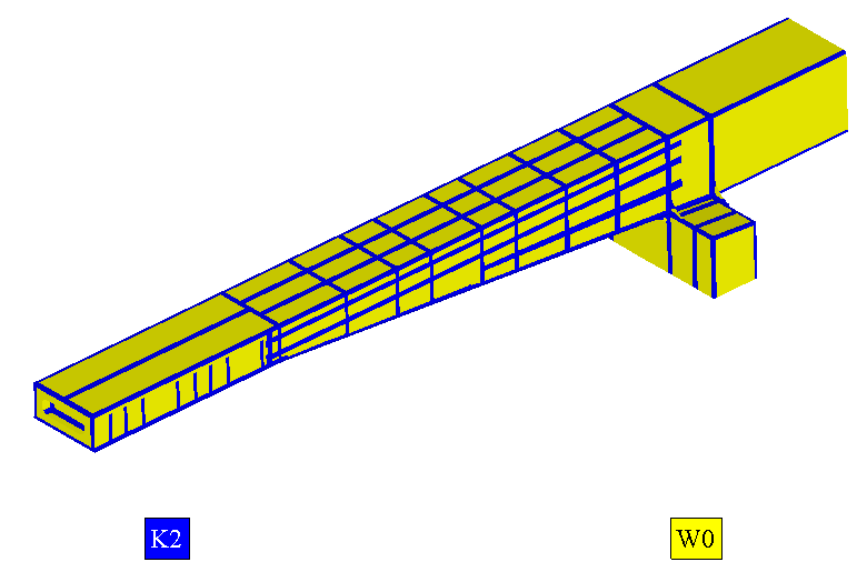
Label Plot
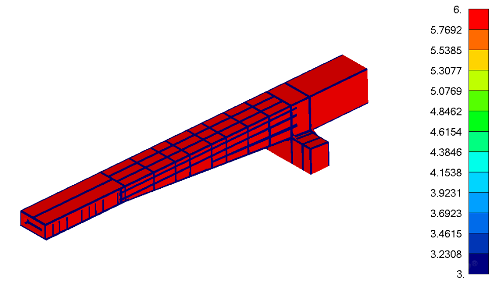
Criteria Plot
Note: Values are calculated condition by condition. If the same element is a part of different conditions - the last condition value is taken. If the element does not belong to any condition - the value from the fist condition is taken.
 -
select welds from Weld Finder and add a list of conditions with empty classification (one weld one condition).
 -
classification stores values in the memory. Clear values from the memory to refresh the classification. Results of checks where classification
is used wil be cleared after pressing OK button.
Classification Condition
Classification condition is applied to the selected directions of the selected elements.
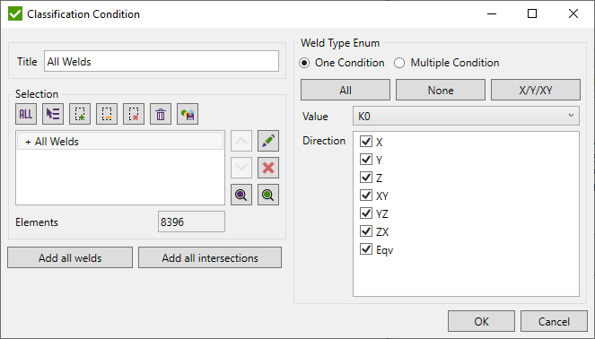
Define Selection to be used in the condition.
One condition - set the value to the selected directions;
Multiple conditions - select the value for each direction separately. The directions with the same values will be grouped in one condition. Other values will form different conditions.
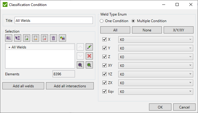
Use , , buttons to operate with selected directions.
Standard Tables
Standard Table is a two-dimensional matrix of static values.
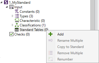
To add Standard Table press Add in Standard Tables context menu:
The following window for parameters setting will be displayed:
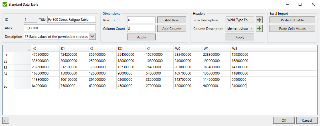
Set table Alias to use it in Custom check formulas.
Set count of rows and columns and press to build the table.
– paste full table from the clipboard.
– paste values from clipboard to cells starting from top left selected cell.
Note: To cut the table set less value for a row or a column count.
It is possible to define a row and a column Headers based on the Types List
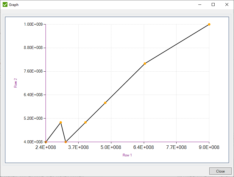
 - display chart of the selected in the following window rows/columns of data to be used for X and Y axes of the chart:
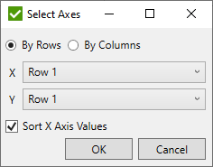
Sort X Axis Values - reorder data selected in rows in ascending order;
Alias
Alias is a unique name for Standard items through which they can be accessed in Custom check formulas.
Note: Alias can contain only letters, digits and underscore symbol ("_"). Alias is unique inside the standard and must be different from the model and result variables such as (Area, Yield, S, Abs, etc.).
Note: Alias of the standard is unique between the standards and must be different from the model and result variables.
Checks
- Custom Check;
- Custom Plate Buckling Check;
- Custom Weld Check;
- Custom Connection Check;
- Custom Rainflow Summation Check;
Common Commands
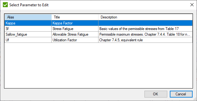
To edit parameter press  .
The dialog box will appear where it is possible to select the necessary parameter to edit.
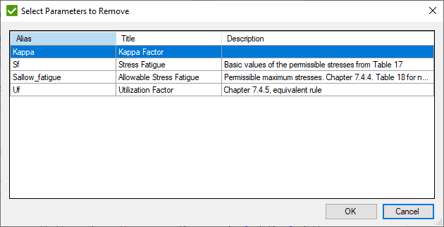
To remove parameters press  .
The dialog box will appear where it is possible to select the necessary parameters to remove.
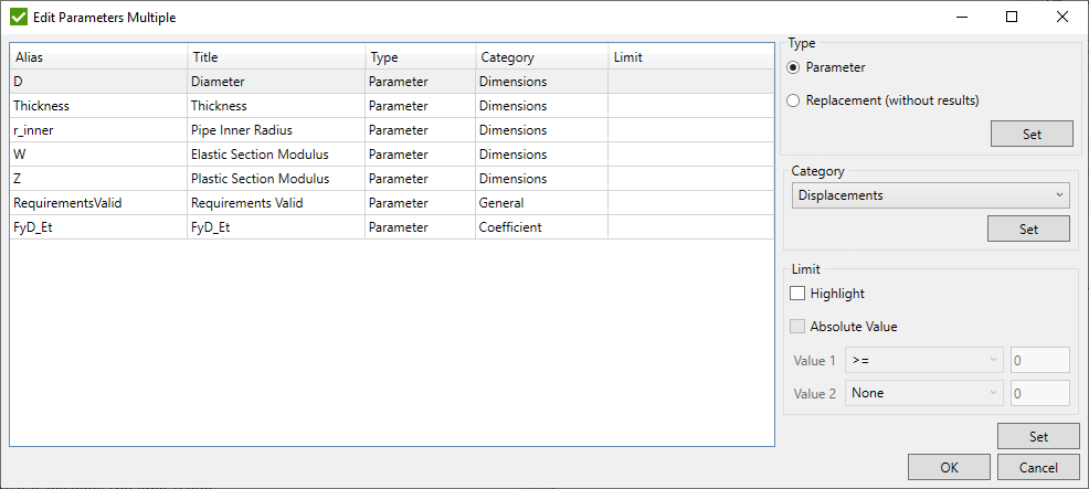
Press  to edit multiple parameters (parameters/replacement, category and limits).
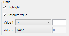
Limits are used to highlight parameters if it exceeds the limit value.
Category defines how parameter will be represented in the table (Number Format) and what Legend Settings will be applied.
E.g. Utilization Factor by default has a general format with 2 digits after the dot:

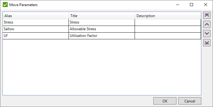
Press  to move parameters:
Custom Check
Custom Check is used in SDC Verifier to perform any user-defined calculations. Custom Check consists of Parameters - formulas are made up of model variables, constants and mathematical operations, results and functions.
There are 4 predefined checks: Static Stress Check, Plate Average Stress, Plate Principal Stresses and Solid Principal Stresses.
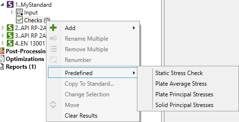
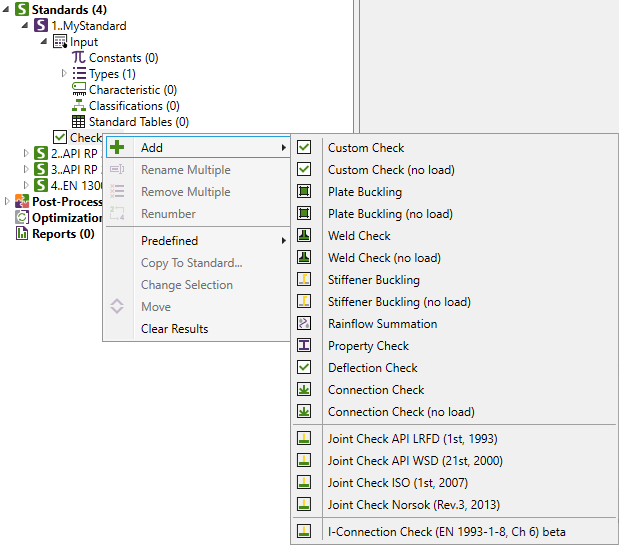
To add Custom Check execute in the checks context menu:
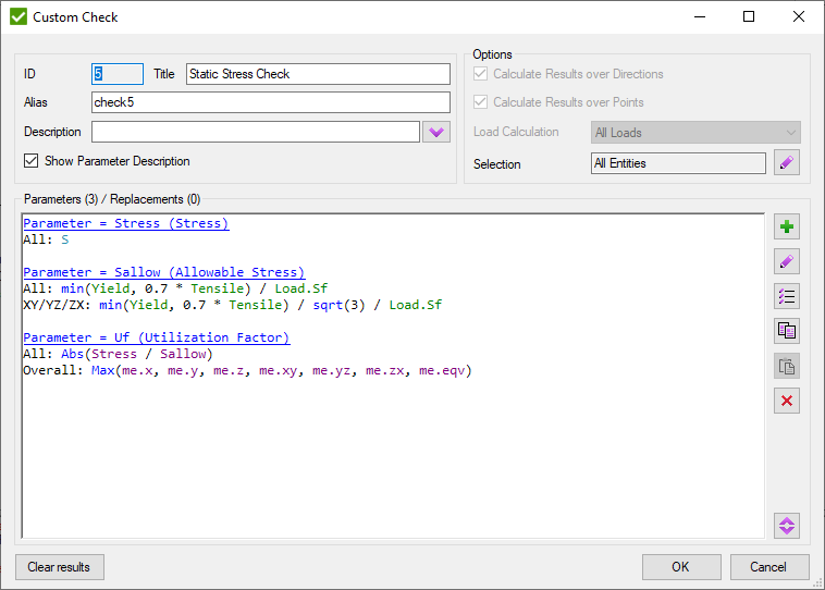
Common commands are described in Common Chapter
Alias - variable name to access it from other checks.
Calculate Results over Directions - calculate for X, Y, Z, XY, YZ, ZX, Equivalent, Overall directions, otherwise one direction is calculated.
Calculate Results over Points - calculate for all element's points of interest, otherwise, one point is calculated.
Note: Calculate Results over Directions and Calculate Results over Points should be defined before the first parameter is selected.
Define Selection (by default all entities) using Selector Control to select entities that will be calculated.
Note: Only part of a model can be selected to reduce the calculation time and quickly obtain results for critical places of the model.
Load calculation can be calculated on All Loads or on Load Groups only.
If All Loads option is used then Load Group is calculated as envelope (like in Job), formulas are calculated for Individual Loads, Load Sets but Load Group is min/max/abs among its items.
If Load Groups option is used then formulas are based on group results, e.g. min/max/abs can be used for stresses, strains, line element force and plane element force.
Note: If Custom Check (no load) is created - Load Calculation Type is disabled.
Add Parameter
To add Parameter to the Custom Check press
 .
For each parameter, the Title and Alias must be defined.
Replacement - means the outcome is intermediate and not stored. The purpose of the replacement is to be used in other parameters from the current check and don't consume memory.
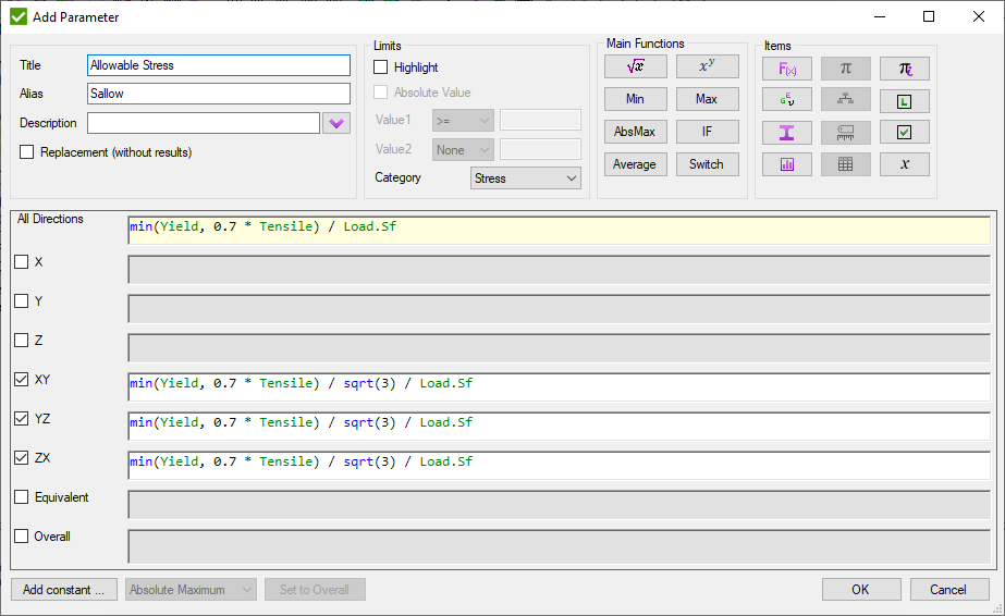
It is possible to create separate formulas for each direction. One formula will be used for all directions if it is inputted into the All Directions text field.
If the formula of a parameter contains logic operations, then the result will be 1 if the condition is fulfilled, else 0 will be assigned to the parameter value.
Note: Formulas in SDC Verifier are case insensitive.
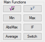
Entities in the Main Functions contains the most important functions containing sqrt(), max(),power(), average(), etc.
All available variables of formulas are collected in the Items
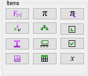
 - Mathematical Operations;
 - Material Variables
(contains characteristics, namely Young modulus, Poisson ratio, mass density, shear modulus, yield limit and tensile strength);
 - Property Variables
(contains the characteristics of model properties such as an area for beam type element, thickness for plate element, cross-section dimensions, etc.);
 - Results Variables (Stress, Strain etc.);
 - Constants from Standard;
 - Characteristics;
 - Classifications;
 - Standard Tables;
 - Inner Constants
(Property Shapes, Yes, No, etc.);
 - Local Check
(contains Parameters already defined in the current Check);
 - Check Parameter. Results from other checks from all existing standards;.
 - Other variables
(beam member, shape, load safety factor).
Adding Items
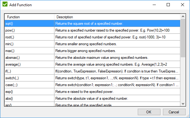
To add a necessary item (all except Results Variables and Check Parameters) press the corresponding button on the Items dialog box. The dialog window appears:
To Add Check Parameter press  .
The dialog window will be shown:
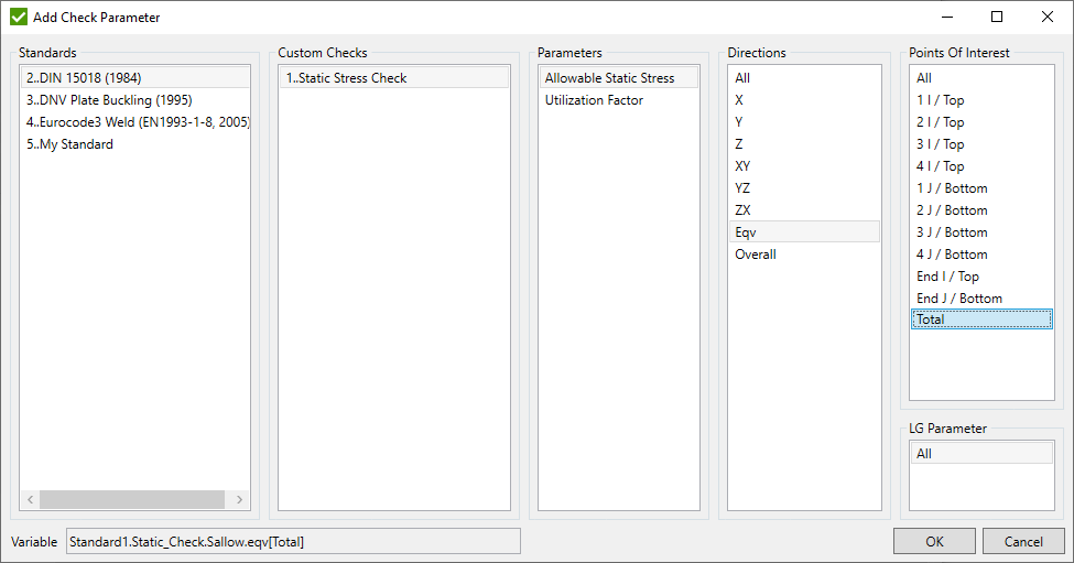
Only standards with ID ≤ current standard ID will be displayed in the list.
Checks are filtered according to the selected check type (e.g. Plate Buckling check can use results only from other Plate Buckling check.) or Load Calculation type (e.g. Custom check cannot use results from Fatigue Summation check).
All Direction/Point of Interest is available if the current check is calculated over directions/points. Otherwise, respective direction/point of interest from the source check should be selected.
To Add Result press  . The dialog window will appear:
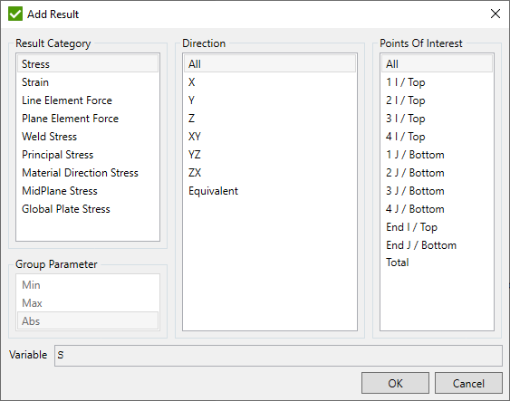
All Direction/Point of Interest is available if the current check is calculated over directions/points. Otherwise, respective direction/point of interest from the selected result should be selected.
Parameters can be edited/copied/removed or converted to characteristic using the popup menu:

Convert to characteristic - create the characteristic of the selected type where the result of parameter will be taken from the characteristic (if characteristic value ≠ 12345678), or will be calculated using the current formula:

If the formula contains items that do not exist for certain element types (e.g. shape height does not exist for shells) then the formula will be evaluated with such items replaced with zero.
Custom check (no load).
Custom check (no load) is a sub-type of Custom Check. Check supports variables that are not based on loads (young modulus, yield stress, property area, a moment of inertia, classification, characteristics, standard table, constants etc.).
Calculate Results over Directions - optional;
Calculate Results over Points - disabled;
Load Calculation - disabled;
Selection - optional;
Property check
Property check is a sub-type of Custom Check. Check supports variables of materials, properties, constants, standard tables. Results are calculated over properties.
Calculate Results over Directions - disabled;
Calculate Results over Points - disabled;
Load Calculation - disabled;
Selection - disabled;
Plate/Stiffener Buckling
The Plate/Stiffener Buckling is used to perform plate buckling calculations with user-defined formulas.
It is very similar to the Custom Check. The major difference is that it is calculated on the section and results presented for the Sections and Plates/Stiffeners. Parameters of plate/stiffener buckling are calculating only for one direction and can use additional variables in formulas: Element Stress (Minimum compression or average) converted into plate direction and Plate dimensions.
To create Plate Buckling check execute in the checks context menu:

Plate Buckling:
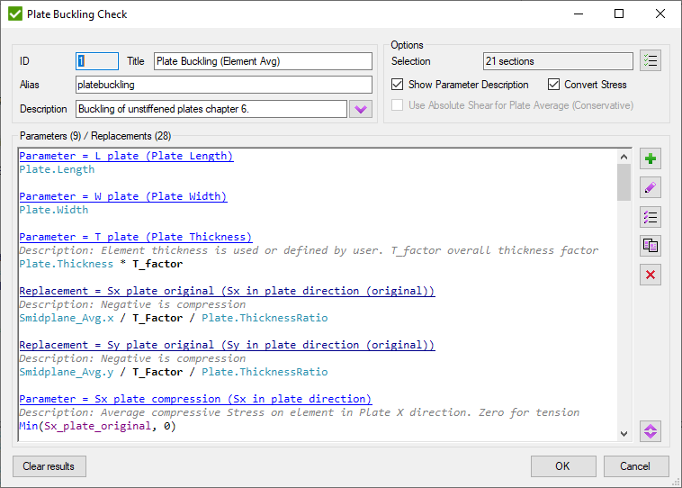
Common commands are described in Common Chapter
By default, all sections are selected to be checked. Press  to change Selection.
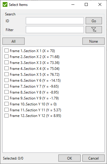
To add Parameter press
 .
For each parameter, the Title and Alias must be defined.
Replacement - means the outcome is intermediate and not stored. The purpose of replacement is to be used in other parameters for the current check but the result is not important for the user.
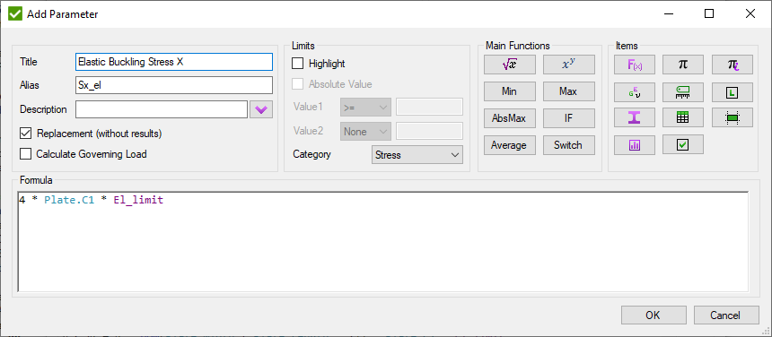
Adding Items
Entities in the Main Functions contains the most important functions containing sqrt(), max(),power(), average(), etc.

All available variables of formulas are collected in the Items
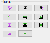
 - Mathematical Operations;
 - Material Variables
(contains characteristics, namely Young modulus, Poisson ratio, mass density, shear modulus, yield limit and tensile strength);
 - Property Variables
(contains the characteristics of the model properties, such as an area for beam type element, thickness for plate element, cross-section dimensions, etc.);
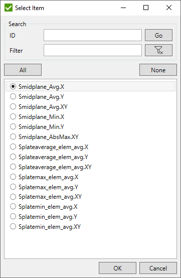
 - Results from plates;
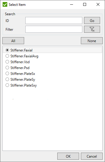
Results from stiffeners;

 - Constants from Standard;
 - Standard Tables;
 - Characteristics;
 - Inner Constants
(Property Shapes, Yes, No, etc.);
 - Local Check
(contains Parameters already defined in the current Plate/Stiffener Buckling Check);
 - Recognition data.
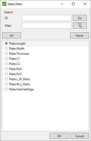
Plates:
Stiffeners:
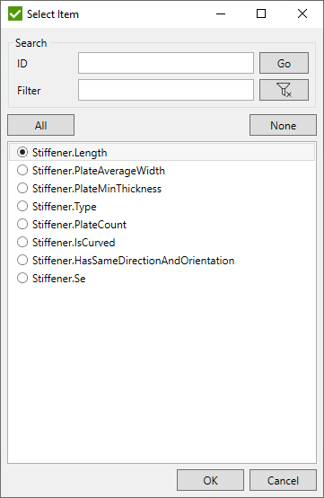
 - Check Parameter.
Results from other checks from all existing standards;
Weld Check
The Weld Check is used to perform weld strength calculations with user-defined formulas.
It is very similar to the Custom Check. The major difference is that it is calculated on the welds. Parameters of weld checks are calculating only for one point of interest and 4 directions (X, Y, XY, Equivalent) and can use additional variables in formulas: Weld Force Summation in weld coordinate system.
To create Weld Check execute in the checks context menu:

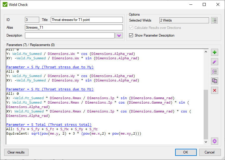
Common commands are described in Common Chapter
By default, all welds are selected to be checked. Press  to change Selection.
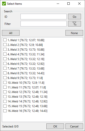
To add Parameter press
 .
For each parameter, the Title and Alias must be defined.
Replacement - means the outcome is intermediate and not stored. The purpose of replacement is to be used in other parameters for the current check but the result is not important for the user.
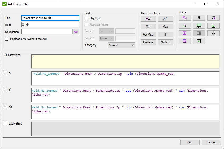
Adding Items
Entities in the Main Functions contains the most important functions containing sqrt(), max(),power(), average(), etc.

All available variables of formulas are collected in the Items
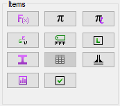
 - Mathematical Operations;
 - Material Variables
(contains characteristics, namely Young modulus, Poisson ratio, mass density, shear modulus, yield limit and tensile strength);
 - Property Variables
(contains the characteristics of the model properties, such as an area for beam type element, thickness for plate element, cross-section dimensions, etc.);
 - Results from
Weld Force Summation Tool;
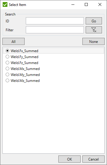
 - Constants from Standard;
 - Standard Tables;
 - Characteristics;
 - Inner Constants
(Property Shapes, Yes, No, etc.);
 - Local Check
(contains Parameters already defined in the current Weld Check);
 - Recognition data.
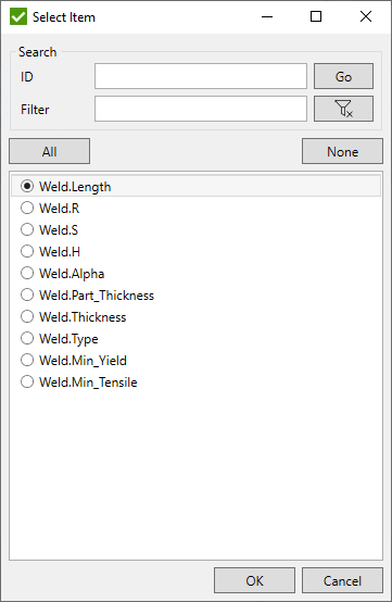
 - Check Parameter.
Results from other checks from all existing standards;
Custom Connection Check
The Connection Check is used to perform calculations of the connections with user-defined formulas.
It is very similar to the Custom Check. The major difference is that it is calculated on the connections. Parameters of connection checks are calculating only for one point of interest and one direction (All) and can use additional variables in formulas: Braces Stress and Brace Classification.
To create Connection Check execute in the checks context menu:


Common commands are described in Common Chapter
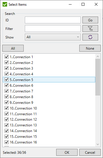
By default, all connections are selected to be checked. Press  to change Selection.
To add Parameter press
 .
For each parameter, the Title and Alias must be defined.
Replacement - means the outcome is intermediate and not stored. The purpose of replacement is to be used in other parameters for the current check but the result is not important for the user.
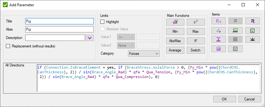
Adding Items
Entities in the Main Functions contains the most important functions containing sqrt(), max(),power(), average(), etc.

All available variables of formulas are collected in the Items
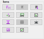
 - Mathematical Operations;
 - Material Variables
(contains characteristics, namely Young modulus, Poisson ratio, mass density, shear modulus, yield limit and tensile strength);
 - Property Variables
(contains the characteristics of the model properties, such as an area for beam type element, thickness for plate element, cross-section dimensions, etc.);
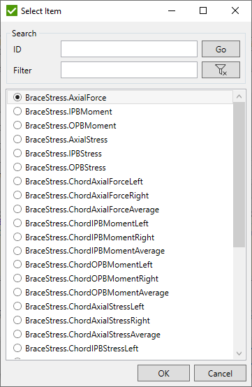
 - Results from
Braces Stress and Brace Classification Tools;
 - Constants from Standard;
 - Standard Tables;
 - Characteristics;
 - Inner Constants
(Property Shapes, Yes, No, etc.);
 - Local Check
(contains Parameters already defined in the current Connection Check);
 - Recognition data.
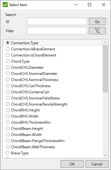
 - Check Parameter.
Results from other checks from all existing standards;
Custom Rainflow Summation Check
The Rainflow Summation Check is used to perform calculations on each direction and point of interest of the element and is based on the Rainflow Counting Tool data with user-defined formulas.
To create Rainflow Summation Check execute in the checks context menu:

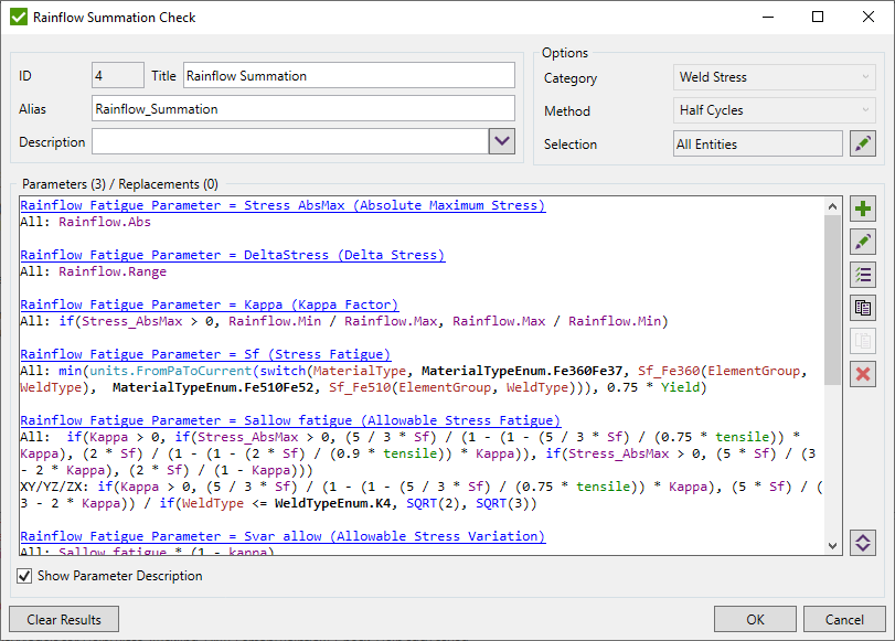
Common commands are described in Common Chapter
Category - category of result from which the Rainflow Counting data will be used;
Method - method from which the Rainflow Counting data will be used;
Selection - part of the model for which the check will be calculated;
Note: Calculations are performed only on Fatigue Groups that contain Load Groups. Therefore, results in tabes/plots can be presented only for these types of loads, depending on selected parameter.
There are 4 types of parameters:
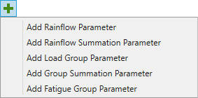
- Rainflow Parameter - performs calculations using the data from Rainflow Counting Tool that depends on Category and Method. Not displayed in the tables/plots;
- Rainflow Summation Parameter - summarizes result for selected Rainflow Parameter and represents result of a Load Group;
- Load Group Parameter - represents result of a Load Group using one or several Rainflow Summation parameters;
- Group Summation Parameter - summarizes result of all Load Groups for selected Rainflow Summation or Load Group parameter and represents result of a Fatigue Group;
- Fatigue Group Parameter - represents result of a Fatigue Group using one or several Group Summation parameters;
For each parameter, the Title and Alias must be defined.
Rainflow Parameter
Performs calculations using the ranges calculated by Rainflow Counting Tool. Result depends on the selected Category and Method in the check. Calculations are performed for each range separately and for each point of interest of the element. Parameter can use Rainflow Counting Variables.
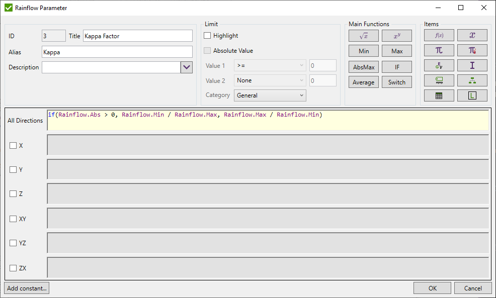
Note: Parameter is calculated only internally and result for it is not stored to result files. Therefore, it is not possible to select it in tables/plots to display the result.
Note: Formulas for Equivalent and Overall directions are not available to be set.
Rainflow Summation Parameter
Parameter is used to summarize result from each of the calculated range for selected Rainflow Parameter and represents result of a Load Group.
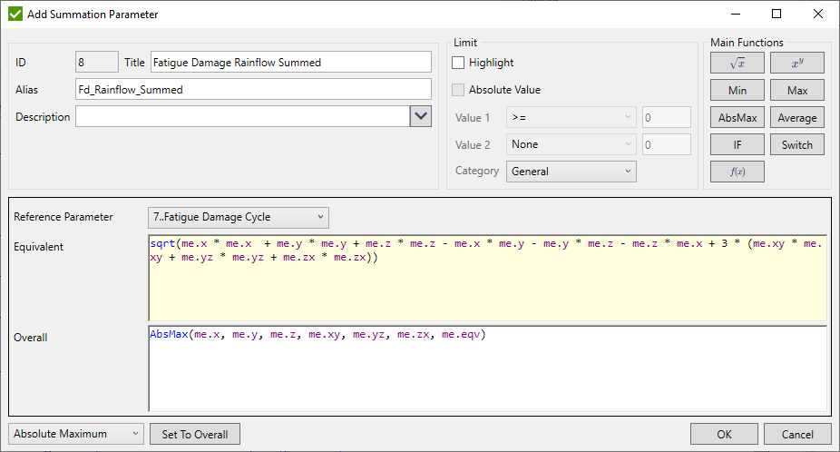
Reference Parameter - Rainflow Parameter from which the results of all calculated ranges will be summarized;
Note: Equivalent and Overall direction can use Functions and summarized results of the calculated directions of current parameter (me.x, me.y etc.).
Rainflow Load Group Parameter
Represents result of a Load Group using one or several Rainflow Summation parameters.
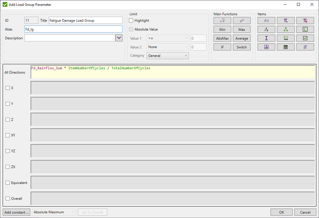
Rainflow Group Summation Parameter
Parameter is used to summarize result of all Load Groups for selected Rainflow Summation Parameter and represents result of a Fatigue Group.
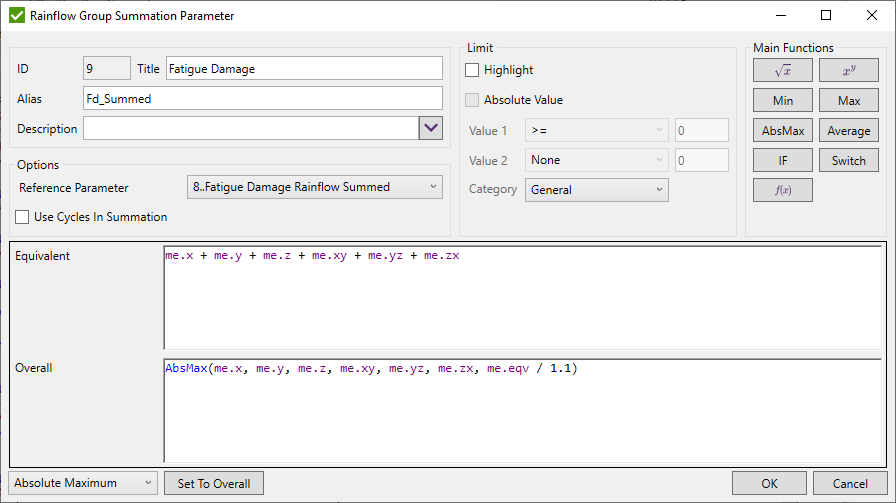
Reference Parameter - Rainflow Summation Parameter for which the results will be calculated for each Load Group defined in Fatigue Group and will be summarized;
Use Cycles in Calculations - optionally use a proportion of the number of cycles defined in Fatigue Group of currently calculated Load Group to the summed number of cycles of all Load Groups in the Fatigue Group. In the formula the following multiplier will be added/removed: ItemNumberOfCycles / TotalNumberOfCycles which represents a portion of the result of the current Load Group comparing to other Load Groups;

Note: Equivalent and Overall direction can use Functions and summarized results of the calculated directions of current parameter (me.x, me.y etc.).
Rainflow Fatigue Group Parameter
Parameter represents result of a Fatigue Group using one or several Group Summation parameters.
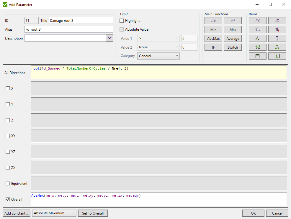
Available Variables:
- Functions;
- Material Variables;
- Property Variables;
- Result Variables;
- Line Element Results Variables;
- Plate / Shell Element Results Variables;
- Plate Buckling Results Variables;
- Plate Dimensions Variables;
- Weld Results Results Variables;
- Weld Dimensions Variables;
- Stiffener Results Variables;
- Stiffener Dimensions Variables;
- Connection Results Variables;
- Connection Dimensions Variables;
- Beam Member Results Variables;
- Beam Member Dimensions Variables;
- Rainflow Counting Variables;
- Other Variables;
Functions
| Variable | Value |
|---|---|
| sqrt() | Returns the square root of a specified number. |
| pow(,) | Returns a specified number raised to the specified power. E.g. Pow(10,2)=100 |
| root(,) | Returns root of specified number of specified power. E.g. root(-1000, 3)=-10 |
| min(,) | Returns smaller among specified numbers. |
| max (,) | Returns bigger among specified numbers. |
| absmax(,) | Returns the absolute maximum value among specified numbers. |
| average(,) | Returns the average value among specified numbers. E.g. Average(1,2,3)=2. |
| if(,,) | If(condition, TrueExpression, FalseExpression).If condition is true then TrueExpression is executer, otherwise FalseExpression. |
| switch(,,) | Returns switch(type, t1, expression1, .., tN, expressionN).If type = t1 then expression1 is executed. |
| exp() | Returns e raised to the specified power. |
| abs() | Returns the absolute value of a specified number. | sin() | Returns the sine of the specified angle. |
| cos() | Returns the cosine of the specified angle. |
| tan() | Returns the tangent of the specified angle. |
| log() | Returns the natural (base e) logarithm of a specified number. |
| round() | Rounds a value to the nearest integer or specified number of decimal places. |
| sign() | Returns a value indicating the sign of a number. |
| sinh() | Returns the hyperbolic sine of the specified angle. |
| cosh() | Returns the hyperbolic cosine of the specified angle. |
| tanh() | Returns the hyperbolic tangent of the specified angle. |
| asin() | Returns the angle whose sine is the specified number. |
| acos() | Returns the angle whose cosine is the specified number. |
| atan() | Returns the angle whose tangent is the specified number. |
| atan2(,) | Returns the angle whose tangent is the quotient of two specified numbers. |
| PI | Mathematical Constant = 3.14159. |
| Interpolate('Standard Table Alias with () brackets', 'X Column Number', 'Y Column Number', 'Input Value to find range from X Column' | Interpolates value of Y Column from the Standard Tables of the standard by setting X and Y column number and value at X column to get the interpolated value; |
Material Variables
| Name | Description |
|---|---|
| young | Young Modulus | poisson | Poisson Ratio |
| shearm | Shear Modulus |
| shear | Shear |
| mdensity | Mass Density |
| tensile | Tensile Strength |
| yield | Yield Stress |
Property Variables
| Name | Description | area | Area |
|---|---|
| nsm | Nonstructural mass |
| torsional | Torsional Constant |
| perimeter | Perimeter |
| coeff | Coefficient for Torsional Stress |
| tension | InitialTension |
| slack | Initial Slack |
| allow_stress | Allowable Tensile Stress |
| area_inertia | Area Moment of Inertia |
| inner | Inner Diametr |
| outer | Outer Diametr |
| pressure | Internal Pressure |
| izz | Moment of Inertia, Izz |
| iyy | Moment of Inertia, Iyy |
| izy | Moment of Inertia, Izy |
| yshear | Y Shear Area |
| zshear | Z Shear Area |
| warping | Warping Constrant |
| yneutral | Y Neutral Axis Offset |
| zneutral | Z Neutral Axis Offset |
| t1 | Thickness 1 |
| t2 | Thickness 2 |
| t3 | Thickness 3 |
| t4 | Thickness 4 |
| topfiber | Top Fiber |
| botfiber | Bottom Fiber |
| tshear | TShear/Mem Thickness |
| stiff | Bend Stiffness |
| DIM1 | Cross section Dimension1 (or Height or Radius) |
| DIM2 | Cross section Dimension2 (or Weight) |
| DIM3 | Cross section Dimension3 (or Weight2) |
| DIM4 | Cross section Dimension42 (or Thickness1) |
| DIM5 | Cross section Dimension5 (or Thickness2) |
| DIM6 | Cross section Dimension6 (or Thickness) |
| H | Cross section Height |
| R | Cross section Radius |
| W1 | Cross section Width 1 |
| W2 | Cross section Width 2 |
| TH1 | Cross section Thickness 1 |
| TH2 | Cross section Thickness 2 |
| T | Cross section Thickness |
| Shape Property | Cross Section Shape |
| stiffened_type | Get cross section stiffened type = {stiffened, unstiffened, combined} |
| WebThickness | Get Section Web Thickness |
| WebWidth | Get Section Web Width |
| WebWidth_NoFlanges | Get Section Web Width between flanges (minus flanges thicknesses) |
| WebArea | Get Section Web Area |
| FlangeTopThickness | Get Section top flange thickness |
| FlangeBottomThickness | Get Section bottom flange thickness |
| SDCSectionType | Get Section SDC Type (I,C,L,T, box or circle) |
| FlangeTopWidth | Get Section top flange width |
| FlangeBottomWidth | Get Section bottom flange width |
| ShapeYOrientation | Get Section Y Axis Orientation (Left, Right, Up or Down) |
| Cbot_Major | Get distance from bottom to neutral line for major axis |
| Cbot_Minor | Get distance from bottom to neutral line for minor axis |
| Ctop_Major | Get distance from top to neutral line for major axis |
| Ctop_Minor | Get distance from top to neutral line for minor axis |
| VerticalAxis | Get Vertical Axis (Y or Z axis oriented up and down in section) |
| Double_Symmetric | Get if shape is double symmetric |
| Section_Height | Get overall section height (calculated by SDC using point of interests) |
| Section_Width | Get overall section width (calculated by SDC using point of interests) |
| Imin | Principal Minimum Moment of Inertia, Imin |
| Imax | Principal Max Moment of Inertia, Imax |
| PrincipleAngle | Princple Angle |
| yc_top | Distance from centroid to the top fibre (along y axis) |
| yc_bot | Distance from centroid to the bottom fibre (along y axis) |
| yc_min | Min distance from centroid to the fibre (along y axis) |
| yc_max | Max distance from centroid to the fibre (along y axis) |
| zc_top | Distance from centroid to the top fibre (along z axis) |
| zc_bot | Distance from centroid to the bottom fibre (along z axis) |
| zc_min | Min distance from centroid to the fibre (along z axis) |
| zc_max | Max distance from centroid to the fibre (along z axis) |
| shapeydistance | Shape distance from bottom/left to the top/right (along y axis) |
| shapezdistance | Shape distance from bottom/left to the top/right (along z axis) |
Results
| Name | Description |
|---|---|
| S | Stress |
| S.x / S.y / S.z | Normal Stresses |
| S.xy / S.yz / S.zx | Shear Stresses |
| S.eqv | Equivalent / Von Mises Stress |
| Smin / Smax / Sabs / Sdelta | Min / Max / Abs / Delta Stress (for Load Group option only) |
| S[1] .. S[8] | Corner Stress |
| S[top] / S[bot] / S[total] | Absolute maximum stress for top corners / bottom corners / all |
Similar as above variables can be used for the following result categories:
| Name | Description |
|---|---|
| SWeld | Weld Stresses for shell elements. Original Stresses will be displayed for the rest of elements. |
| SWeld.X | Stress parallel to the weld direction |
| SWeld.Y | Stress perpendicular to the weld direction |
| SWeld.XY | Shear stress in weld direction |
| S_HotSpot | Hot Spot Stresses. Original Stresses or 0 (depends on the option defined in Job Settings of calculated load) will be displayed for the elements without hot spot locations defined. |
| SMat | Material Stresses for shell elements. Original Stresses will be displayed for the rest of elements. |
| SMidp | Mid-Plane Stresses for shell elements. Original Stresses will be displayed for the rest of elements. |
| SGlobalp | Global Plate Stresses for shell elements. Original Stresses will be displayed for the rest of elements. Equivalent direction cannot be used. |
| St | Strain |
| SPrin.Max / SPrin.Min / SPrin.Int / SPrin.MaxShear / SPrin.Angle | Max / Min / Int / Max Shear / Principal Angle of the Principal Stresses results; |
Line Element Results
| Name | Description |
|---|---|
| Mbend1 / Mbend2 | Bending Plane Moment (local element plane XY / YZ) |
| Fshear1 / Fshear2 | Shear Force 1 (local element plane XY / XZ) |
| Faxial | Axial Force |
| Ftorque | Torque Force |
| Fwarping_torque | Wapring Force |
| Faxial.Min / Faxial.Max / Faxial.Abs / Faxial. Delta | Min / Max / Abs / Delta Axial Force (for Load Group option only) |
| Faxial[top] / Faxial[bot] | Axial Force on start / end |
Plate / Shell Element Results
| Name | Description |
|---|---|
| FmembraneX / FmembraneY / FMembraneXY | Membrane Force X |
| MbendX / MbendY / MbendXY | Bending Moment X/Y/XY |
| FtransShearX / FTransShearY | Trans Shear Force X/Y |
| FmembraneX.Min / FmembraneX.Max / FmemberaneX.Abs | dMin / Max / Abs membrane force (for load group) |
| FmembraneX[1] .. FmembraneX[4] | Corner result for membrane force |
Plate Buckling Results
| Name | Description |
|---|---|
| Smidplane_Avg.X/Y/XY | Average midplane stress in X/Y/XY directions |
| Smidplane_Min.X/Y | Minimum midplane stress in X/Y directions |
| Smidplane_Abs.XY | Absolute Maximum midplane stress in XY direction |
| Splateaverage_elem_avg.X/Y/XY | Averaged Stress over buckling plate (Element Average Stress) |
| Splatemax_elem_avg.X/Y/XY | Max Stress over buckling plate (Element Average Stress) |
| Splatemin_elem_avg.X/Y/XY | Min Stress over buckling plate (Element Average Stress) |
Plate Dimensions
Values obtained from Panel Finder Tool.
| Name | Description |
|---|---|
| Plate.Length | Plate length |
| Plate.Width | Plate width |
| Plate.Thickness | Thickness of currently calculated element of the plate |
| Plate.ThicknessRatio | Ratio of user defined thickness to currently calculated element of the plate |
| Plate.C1 | Coefficient C1 used in ABS Plate Buckling standards |
| Plate.C2 | Coefficient C2 used in ABS Plate Buckling standards |
| Plate.PsiX | Coefficient PsiX used in DNV 1995 Plate Buckling standard |
| Plate.PsiY | Coefficient PsiY used in DNV 1995 Plate Buckling standard |
| Plate.L_W_Ratio | Plate length to width ratio |
| Plate.W_L_Ratio | Plate width to length ratio |
| Plate.HasFreeEdge | Check if plate has free edges |
Weld Results
Results obtained from Weld Summation Tool.
| Name | Description |
|---|---|
| Weld.Fx_Summed_Element | AbsMax force X on element from converted into averaged csys of the element corners |
| Weld.Fy_Summed_Element | AbsMax force Y on element from converted into averaged csys of the element corners |
| Weld.Fz_Summed_Element | AbsMax force XY on element from converted into averaged csys of the element corners |
| Weld.Mx_Summed_Element | AbsMax moment X on element from converted into averaged csys of the element corners |
| Weld.My_Summed_Element | AbsMax moment Y on element from converted into averaged csys of the element corners |
| Weld.Mz_Summed_Element | AbsMax moment XY on element from converted into averaged csys of the element corners |
Weld Dimensions
Values obtained from Weld Finder Tool.
| Name | Description |
|---|---|
| Weld.Length | Weld length |
| Weld.Element_Length | Weld length calculated by elemental method from weld summation tool |
| Weld.Part_Thickness | Plate thickness or minimum thickness of all walls of the beam |
| Weld.R | Weld leg horizontal |
| Weld.S | Weld penetration depth |
| Weld.H | Weld leg vertical |
| Weld.Thickness | Weld throat thickness |
| Weld.Alpha | Weld angle |
| Weld.Type | Type of the weld. Can be compared with inner constants: WeldType_None, WeldType_DoubleFullPenetration, WeldType_DoublePartialPenetration, WeldType_DoubleFillet, WeldType_SingleFillet |
| Weld.Side | Side of the weld for Single Fillet weld type. Can be compared with inner constants: WeldSide_PlusY, WeldSide_MinusY |
Stiffener Results
Results obtained from Effective Plate Width Tool.
| Name | Description |
|---|---|
| Stiffener.Faxial | Axial Force in stiffener element |
| Stiffener.FaxialAvg | Average axial force |
| Stiffener.Psd | Design Lateral Pressure |
| Stiffener.Vsd | Shear Force in stiffener element |
| Stiffener.PlateSx | Averaged plate stresses of half of plates elements connected to the stiffener parallel to the stiffener |
| Stiffener.PlateSy | Averaged plate stresses of half of plates elements connected to the stiffener perpendicular to the stiffener |
| Stiffener.PlateSxy | Averaged plate shear stresses of half of plates elements connected to the stiffener |
| Stiffener.Se | Effective Stiffener Width |
Stiffener Dimensions
Values obtained from Panel Finder Tool.
| Name | Description |
|---|---|
| Stiffener.Length | Length of the stiffener |
| Stiffener.PlateAverageWidth | Averaged width of all connected plates to the stiffener |
| Stiffener.PlateMinThickness | Minimum plate thickness |
| Stiffener.Type | Continuous or snipped |
| Stiffener.PlateCount | Count of connected plates |
| Stiffener.IsCurved | Check is stiffener is curved |
| Stiffener.HasSameDirectionAndOrientation | Check if all elements in stiffener has same orientation |
Connection Results
Results obtained from Braces Stress and Brace Classification tools. Following list of variables get result of the currently calculated brace. Same variables can be used from to get result from any brace of the connection by replacing BraceStress or Brace with Connection.Upper/Lower.Brace1/Brace2/Brace3 (e.g. Connection.Upper.Brace2.AxialForce will return axial force from the second upper brace of the connection).
| Name | Description |
|---|---|
| BraceStress.AxialForce, Brace.AxialForce | Axial force of the brace |
| BraceStress.IPBMoment, Brace.IPBMoment | Bending moment in plane of connection of the brace |
| BraceStress.OPBMoment, Brace.OPBMoment | Bending moment out of plane of connection of the brace |
| BraceStress.AxialStress, Brace.AxialStress | Axial stress of the brace |
| BraceStress.IPBStress, Brace.IPBStress | Bending stress in plane of connection of the brace |
| BraceStress.OPBStress, Brace.OPBStress | Bending stress out of plane of connection of the brace |
| BraceStress.ChordAxialForceLeft, Brace.ChordAxialForceLeft | Axial force of the chord from the left element at Brace-Chord joint node |
| BraceStress.ChordAxialForceRight, Brace.ChordAxialForceRight | Axial force of the chord from the right element at Brace-Chord joint node |
| BraceStress.ChordAxialForceAverage, Brace.ChordAxialForceAverage | Average axial force of the chord at Brace-Chord joint node |
| BraceStress.IPBMomentLeft, Brace.IPBMomentLeft | Bending moment in plane of connection of the chord from the left element at Brace-Chord joint node |
| BraceStress.IPBMomentRight, Brace.IPBMomentRight | Bending moment in plane of connection of the chord from the right element at Brace-Chord joint node |
| BraceStress.IPBMomentAverage, Brace.IPBMomentAverage | Average bending moment in plane of connection of the chord at Brace-Chord joint node |
| BraceStress.OPBMomentLeft, Brace.OPBMomentLeft | Bending moment out of plane of the chord from the left element at Brace-Chord joint node |
| BraceStress.OPBMomentRight, Brace.OPBMomentRight | Bending moment out of plane of the chord from the right element at Brace-Chord joint node |
| BraceStress.OPBMomentAverage, Brace.OPBMomentAverage | Average bending moment out of plane of the chord at Brace-Chord joint node |
| BraceStress.ChordAxialStressLeft, Brace.ChordAxialStressLeft | Axial stress of the chord from the left element at Brace-Chord joint node |
| BraceStress.ChordAxialStressRight, Brace.ChordAxialStressRight | Axial stress of the chord from the right element at Brace-Chord joint node |
| BraceStress.ChordAxialStressAverage, Brace.ChordAxialStressAverage | Average axial stress of the chord at Brace-Chord joint node |
| BraceStress.IPBStressLeft, Brace.IPBStressLeft | Bending stress in plane of connection of the chord from the left element at Brace-Chord joint node |
| BraceStress.IPBStressRight, Brace.IPBStressRight | Bending stress in plane of connection of the chord from the right element at Brace-Chord joint node |
| BraceStress.IPBStressAverage, Brace.IPBStressAverage | Average bending stress in plane of connection of the chord at Brace-Chord joint node |
| BraceStress.OPBStressLeft, Brace.OPBStressLeft | Bending stress out of plane of the chord from the left element at Brace-Chord joint node |
| BraceStress.OPBStressRight, Brace.OPBStressRight | Bending stress out of plane of the chord from the right element at Brace-Chord joint node |
| BraceStress.OPBStressAverage, Brace.OPBStressAverage | Average bending stress out of plane of the chord at Brace-Chord joint node |
| BraceTypeLefToRight.K, Brace.BraceTypeKTotalForce | Percentage of K Type using Left-to-Right method |
| BraceTypeLefToRight.Ty, Brace.BraceTypeTyTotalForce | Percentage of TY Type using Left-to-Right method |
| BraceTypeLefToRight.Cross, Brace.BraceTypeCrossTotalForce | Percentage of Cross Type using Left-to-Right method |
| BraceTypeLefToRight.TotalGap, Brace.BraceTypeTotalGapTotalForce | Sum of all gaps multiplied on percentage of each that depends on the percentage of the taken load using Left-to-Right method |
| BraceTypeTotalForce.K, Brace.BraceTypeKLeftToRight | Percentage of K Type using Total Forces method |
| BraceTypeTotalForce.Ty, Brace.BraceTypeTyLeftToRight | Percentage of TY Type using Total Forces method |
| BraceTypeTotalForce.Cross, Brace.BraceTypeCrossLeftToRight | Percentage of Cross Type using Total Forces method |
| BraceTypeTotalForce.TotalGap, Brace.BraceTypeTotalGapLeftToRight | Sum of all gaps multiplied on percentage of each that depends on the percentage of the taken load using Total Forces method |
| Brace.IPShearForce | Shear force in plane of connection of the brace |
| Brace.OPShearForce | Shear force out of plane of connection of the brace |
| Brace.TorsionalMoment | Torsional moment of connection of the brace |
Following list of variables get result from all the braces in the connection (e.g. summed or absmax axial force from all braces of the connection)
| Name | Description |
|---|---|
| BraceStress.SumIPBMomentUpperBraces | Summed in plane bending moment from all upper braces of the connection |
| BraceStress.SumOPBMomentUpperBraces | Summed out of plane bending moment from all upper braces of the connection |
| BraceStress.SumAxialForceLowerBraces | Summed axial force from all lower braces of the connection |
| BraceStress.SumPerpendicularAxialForceLowerBraces | Summed axial force perpendicular to the chord from all lower braces of the connection |
| BraceStress.SumParallelAxialForceLowerBraces | Summed axial force parallel to the chord from all lower braces of the connection |
| BraceStress.SumIPBMomentLowerBraces | Summed in plane bending moment from all lower braces of the connection |
| BraceStress.SumOPBMomentLowerBraces | Summed out of plane bending moment from all lower braces of the connection |
| BraceStress.SumAxialStressUpperBraces | Summed axial stress from all upper braces of the connection |
| BraceStress.SumPerpendicularAxialStressUpperBraces | Summed axial stress (using axial force perpendicular to the chord) from all upper braces of the connection |
| BraceStress.SumParallelAxialStressUpperBraces | Summed axial stress (using axial force parallel to the chord) from all upper braces of the connection |
| BraceStress.SumIPBStressUpperBraces | Summed in plane bending stress from all upper braces of the connection |
| BraceStress.SumOPBStressUpperBraces | Summed out of plane bending stress from all upper braces of the connection |
| BraceStress.SumAxialStressLowerBraces | Summed axial stress from all lower braces of the connection |
| BraceStress.SumPerpendicularAxialStressLowerBraces | Summed axial stress (using axial force perpendicular to the chord) from all lower braces of the connection |
| BraceStress.SumParallelAxialStressLowerBraces | Summed axial stress (using axial force parallel to the chord) from all lower braces of the connection |
| BraceStress.SumIPBStressLowerBraces | Summed in plane bending stress from all lower braces of the connection |
| BraceStress.SumOPBStressLowerBraces | Summed out of plane bending stress from all lower braces of the connection |
| BraceStress.BraceAbsMaxForceParallel | Absolute maximum axial force parallel to the chord from all braces of the connection |
| BraceStress.BraceAbsMaxForcePerpendicular | Absolute maximum axial force perpendicular to the chord from all braces of the connection |
| BraceStress.ChordMinAxialForce | Minimum axial force of all chord elements |
| BraceStress.ChordMaxAxialForce | Maximum axial force of all chord elements |
| BraceStress.ChordAbsMaxAxialForce | Absolute Maximum axial force of all chord elements |
| BraceStress.ChordAbsMaxAxialForceInGap | Absolute maximum value of summed axial forces parallel to the chord of the chord element and all braces from the same side of the joint node |
Connection Dimensions
Values obtained from Connection Finder Tool and additionally calculated values
| Name | Description |
|---|---|
| Connection.Type | Return type of connection. Comparison in formulas can be done with inner constants: ConnectionType_CHS, ConnectionType_RHS, ConnectionType_IBeam, ConnectionType_Combined |
| Connection.IsBraceElement | Checks if currently calculated element of the connection belongs to braces |
| Connection.IsChordElement | Checks if currently calculated element of the connection belongs to chord |
| Connection.Upper | Access the variables of upper braces Brace1, Brace2, Brace3 of the connection |
| Connection.Lower | Access the variables of lower braces Brace1, Brace2, Brace3 of the connection |
| Connection.Upper.Brace1.CHS | Access the following results of the first upper brace of connection: Diameter, Thickness, L, L1, L2, Ov, Q. If brace is not circular shape or brace does not exist - 0 result is returned. Similarly, Brace2 and Brace3 can be used: Connection.Upper.Brace2.CHS, Connection.Upper.Brace3.CHS |
| Connection.Upper.Brace1.RHS | Access the following results of the first upper brace of connection: Height, Width, ThicknessMin, Ov, Q. If brace is not rectangular shape or brace does not exist - 0 result is returned. Similarly, Brace2 and Brace3 can be used: Connection.Upper.Brace2.RHS, Connection.Upper.Brace3.RHS |
| Connection.Upper.Brace1.IBeam | Access the following results of the first upper brace of connection: Height, Width, FlangeThicknessMin, WebThickness. If brace is not I-Beam shape or brace does not exist - 0 result is returned. Similarly, Brace2 and Brace3 can be used: Connection.Upper.Brace2.IBeam, Connection.Upper.Brace3.IBeam |
| Connection.Lower.Brace1.CHS | Access the following results of the first lower brace of connection: Diameter, Thickness, L, L1, L2, Ov, Q. If brace is not circular shape or brace does not exist - 0 result is returned. Similarly, Brace2 and Brace3 can be used: Connection.Lower.Brace2.CHS, Connection.Lower.Brace3.CHS |
| Connection.Lower.Brace1.RHS | Access the following results of the first lower brace of connection: Height, Width, ThicknessMin, Ov, Q. If brace is not rectangular shape or brace does not exist - 0 result is returned. Similarly, Brace2 and Brace3 can be used: Connection.Lower.Brace2.RHS, Connection.Lower.Brace3.RHS |
| Connection.Lower.Brace1.IBeam | Access the following results of the first lower brace of connection: Height, Width, FlangeThicknessMin, WebThickness. If brace is not I-Beam shape or brace does not exist - 0 result is returned. Similarly, Brace2 and Brace3 can be used: Connection.Lower.Brace2.IBeam, Connection.Lower.Brace3.IBeam |
| GapToCurrentBrace | Gap distance (negative value for overlapping) from one of the braces to currently calculated brace. Can be accessed for following braces: Connection.Upper.Brace1, Connection.Upper.Brace2, Connection.Upper.Brace3, Connection.Lower.Brace1, Connection.Lower.Brace2, Connection.Lower.Brace3 |
| EccentricityWithCurrentBrace | Get eccentricity value from one of the braces with currently calculated brace. Can be accessed for following braces: Connection.Upper.Brace1, Connection.Upper.Brace2, Connection.Upper.Brace3, Connection.Lower.Brace1, Connection.Lower.Brace2, Connection.Lower.Brace3 |
| IsOverlappingForCurrentBrace | Checks if one of the braces is overlapping with currently calculated brace. Can be accessed for following braces: Connection.Upper.Brace1, Connection.Upper.Brace2, Connection.Upper.Brace3, Connection.Lower.Brace1, Connection.Lower.Brace2, Connection.Lower.Brace3 |
| Connection.SumBracesHeights | Summed height (cross section size in plane of connection) of all the braces of the connection |
| Connection.SumBracesHeightsUpper | Summed height of all upper braces of the connection |
| Connection.SumBracesHeightsLower | Summed height of all lower braces of the connection |
| Connection.SumBracesWidths | Summed width (cross section size out of plane of connection) of all the braces of the connection |
| Connection.SumBracesWidthsUpper | Summed width of all upper braces of the connection |
| Connection.SumBracesWidthsLower | Summed width of all lower braces of the connection |
| Connection.BracesCount | Amount of all braces of the connection |
| Connection.UpperBracesCount | Amount of upper braces of the connection |
| Connection.LowerBracesCount | Amount of lower braces of the connection |
| Chord.Type | Return type of the chord. Comparison in formulas can be done with inner constants: ChordType_CHS, ChordType_RHS, ChordType_IBeam |
| ChordCHS.Diameter | Maximum diameter of all chord CHS elements if Can is found or minimum diameter otherwise |
| ChordCHS.NominalDiameter | Minimum diameter of all chord CHS elements |
| ChordCHS.NominalThickness | Minimum thickness of all chord CHS elements |
| ChordCHS.CanThickness | Maximum thickness of all chord CHS elements if Can is found or minimum thickness otherwise |
| ChordCHS.ContainsCan | Checks if chord contains Can for CHS cross sections |
| ChordCHS.NominalYieldStress | Yield Stress of the CHS element of the chord with minimum thickness |
| ChordCHS.NominalTensileStrength | Tensile Strength of the CHS element of the chord with minimum thickness |
| ChordRHS.Height | Minimum height in plane of connection of all chord RHS elements |
| ChordRHS.Width | Minimum width out of plane of connection of all chord RHS elements |
| ChordRHS.ThicknessMin | Minimum thickness of all chord RHS elements |
| ChordIBeam.Height | Minimum height in plane of connection of all chord I-Beam elements |
| ChordIBeam.Width | Minimum width out of plane of connection of all chord I-Beam elements flanges |
| ChordIBeam.FlangeThicknessMin | Minimum flange thickness of all chord I-Beam elements |
| ChordIBeam.WebThickness | Minimum web thickness of all chord I-Beam elements |
| Brace.Type | Return type of the currently calculated brace. Comparison in formulas can be done with inner constants: BraceType_CHS, BraceType_RHS, BraceType_IBeam |
| Brace.ElementId | Element ID of the currently calculated brace |
| Brace.Height | Cross section height (size in plane of connection) of the currently calculated brace |
| Brace.Width | Cross section width (size out of plane of connection) of the currently calculated brace |
| Brace.Number | Number of brace in the connection of the currently calculated brace |
| Brace.NumberUpper | Number of the upper brace in the connection of the currently calculated brace. Return 0 if current brace is lower |
| Brace.NumberLower | Number of the lower brace in the connection of the currently calculated brace. Return 0 if current brace is upper |
| Brace.IsUpper | Checks if currently calculated brace is upper |
| Brace.IsLower | Checks if currently calculated brace is lower |
| Brace.IsOverlapping | Checks if currently calculated brace is overlapping |
| Brace.Angle | Angle of currently calculated brace to the chord in degrees. Range is [0; 90] |
| Brace.EffectiveLength | Effective Length (distance from the brace to the end of chord Can) of currently calculated brace for CHS connections if Can is found |
| Brace.Yield | Yield Stress of currently calculated brace |
| Brace.Tensile | Tensile Strength of currently calculated brace |
| Brace.Young | Young's Modulus of currently calculated brace |
| Brace.IsDifferentChordPropertyAtJoint | Checks if chord has different property sizes of the chord at the Brace-Chord joint node |
| Brace.ChordYieldStressAtJointLeft | Yield Stress of the left element of the chord at the Brace-Chord joint node |
| Brace.ChordYieldStressAtJointRight | Yield Stress of the right element of the chord at the Brace-Chord joint node |
| Brace.ChordYieldStressAtJointAverage | Average Yield Stress of the of the chord elements at the Brace-Chord joint node |
| Brace.ChordTensileStrengthAtJointLeft | Tensile Strength of the left element of the chord at the Brace-Chord joint node |
| Brace.ChordTensileStrengthAtJointRight | Tensile Strength of the right element of the chord at the Brace-Chord joint node |
| Brace.ChordTensileStrengthAtJointAverage | Average Tensile Strength of the of the chord elements at the Brace-Chord joint node |
| Brace.ChordYoungAtJointLeft | Young's Modulus of the left element of the chord at the Brace-Chord joint node |
| Brace.ChordYoungAtJointRight | Young's Modulus of the right element of the chord at the Brace-Chord joint node |
| Brace.ChordYoungAtJointAverage | Average Young's Modulus of the of the chord elements at the Brace-Chord joint node |
| BraceCHS.Thickness | Thickness of currently calculated CHS brace |
| BraceCHS.Diameter | Diameter of currently calculated CHS brace |
| BraceCHS.L | Thickness of currently calculated CHS brace |
| BraceCHS.L1 | Thickness of currently calculated CHS brace |
| BraceCHS.L2 | Thickness of currently calculated CHS brace |
| BraceCHS.Ov | Thickness of currently calculated CHS brace |
| BraceCHS.Q | Thickness of currently calculated CHS brace |
| BraceRHS.Height | Height of currently calculated RHS brace in plane of connection |
| BraceRHS.Width | Height of currently calculated RHS brace out of plane of connection |
| BraceRHS.ThicknessMin | Minimum thickness of currently calculated RHS brace |
| BraceIBeam.Height | Height of currently calculated I-Beam brace in plane of connection |
| BraceIBeam.Width | Width of currently calculated I-Beam brace out of plane of connection |
| BraceIBeam.FlangeThicknessMin | Minimum flange thickness of currently calculated I-Beam brace |
| BraceIBeam.WebThickness | Web thickness of all chord I-Beam elements |
The following functions can be also used to obtain results between two braces of connection:
| Name | Description |
|---|---|
| GapBetweenBracesUpper(br1, br2) | Calculate geometrical distance between two upper braces of connection on the chord shell. Br1, Br2 - numbers of upper brace in connection. |
| GapBetweenBracesLower(br1, br2) | Calculate geometrical distance between two lower braces of connection on the chord shell. Br1, Br2 - numbers of lower braces in connection. |
| AngleBetweenBracesUpper(br1, br2) | Angle between two upper braces in radians. Br1, Br2 - numbers of upper brace in connection. |
| AngleBetweenBracesLower(br1, br2) | Angle between two lower braces in radians. Br1, Br2 - numbers of lower brace in connection. |
Beam Member Results
Results of Moment Ratio Tool
| Variable | Value |
|---|---|
| Tool.MaxMomentY, MemberY.MaxMoment | Max moment over member in Y direction. |
| Tool.MaxMomentZ, MemberZ.MaxMoment | Max moment over member in Z direction |
| MemberTorsional.MaxMomentY, MemberTorsional.MaxMomentZ | Max moment over torsional member in Y/Z direction |
| MemberY.MaxPrinMoment, MemberZ.MaxPrinMoment | Max principal moment over member in Y/Z direction |
| MemberTorsional.MaxPrinMomentY, MemberTorsional.MaxPrinMomentZ | Max principal moment over torsional member in Y/Z direction |
| MemberY.MaxMomentOnEnd, MemberZ.MaxMomentOnEnd | Max moment of member ends in Y/Z direction |
| MemberTorsional.MaxMomentOnEndY, MemberTorsional.MaxMomentOnEndZ | Max moment of torsional member ends in Y/Z direction |
| MemberY.MaxPrinMomentOnEnd, MemberZ.MaxPrinMomentOnEnd | Max principal moment of member ends in Y/Z direction |
| MemberTorsional.MaxPrinMomentOnEndY, MemberTorsional.MaxPrinMomentOnEndZ | Max principal moment of torsional member ends in Y/Z direction |
| MemberY.IsMaxMomentOnEnd, MemberZ.IsMaxMomentOnEnd | Checks if max moment of full member is located at member ends in Y/Z direction |
| MemberTorsional.IsMaxMomentOnEndY, MemberTorsional.IsMaxMomentOnEndZ | Checks if max moment of torsional member is located at member ends in Y/Z direction |
| MemberY.IsMaxPrinMomentOnEnd, MemberZ.IsMaxPrinMomentOnEnd | Checks if max principal moment of member is located at member ends in Y/Z direction |
| MemberTorsional.IsMaxPrinMomentOnEndY, MemberTorsional.IsMaxPrinMomentOnEndZ | Checks if max principal moment of torsional member is located at member ends in Y/Z direction |
| Tool.MinMomentY, MemberY.MinMoment | Min moment over member in Y direction |
| Tool.MinMomentZ, MemberZ.MinMoment | Min moment over member in Z direction |
| MemberTorsional.MinMomentY, MemberTorsional.MinMomentZ | Min moment over torsional member in Y/Z direction |
| MemberY.MinPrinMoment, MemberZ.MinPrinMoment | Min principal moment over member in Y/Z direction |
| MemberTorsional.MinPrinMomentY, MemberTorsional.MinPrinMomentZ | Min principal moment over torsional member in Y/Z direction |
| MemberY.MinMomentOnEnd, MemberZ.MinMomentOnEnd | Min moment of member ends in Y/Z direction |
| MemberTorsional.MinMomentOnEndY, MemberTorsional.MinMomentOnEndZ | Min moment of torsional member ends in Y/Z direction |
| MemberY.MinPrinMomentOnEnd, MemberZ.MinPrinMomentOnEnd | Min principal moment of member ends in Y/Z direction |
| MemberTorsional.MinPrinMomentOnEndY, MemberTorsional.MinPrinMomentOnEndZ | Min principal moment of torsional member ends in Y/Z direction |
| Tool.M1M2Ratio_Y, MemberY.M1M2RatioOnEnd | Moment ratio over member ends in Y direction |
| Tool.M1M2Ratio_Z, MemberZ.M1M2RatioOnEnd | Moment ratio over member ends in Z direction |
| Tool.M1M2RatioTorsionalY, MemberTorsional.M1M2RatioOnEndZ | Moment ratio over torsional member ends in Y/Z direction |
| MemberY.M1M2PrinRatioOnEnd, MemberZ.M1M2PrinRatioOnEnd | Principal moment ratio over member ends in Y/Z direction |
| MemberTorsional.M1M2PrinRatioOnEndY, MemberTorsional.M1M2PrinRatioOnEndZ | Principal moment ratio over torsional member ends in Y/Z direction |
| Tool.Kc_Y, MemberY.Kc | Kc coefficient (Eurocode3) of member in Y direction |
| Tool.Kc_Z, MemberZ.Kc | Kc coefficient (Eurocode3) of member in Z direction |
| MemberTorsional.KcY, MemberTorsional.KcZ | Kc coefficient (Eurocode3) of torsional member in Y/Z direction |
| MemberY.KcPrin, MemberZ.KcPrin | Kc coefficient (Eurocode3) of member in Y/Z direction using moments in principal axes |
| MemberTorsional.KcPrinY, MemberTorsional.KcPrinZ | Kc coefficient (Eurocode3) of torsional member in Y/Z direction using moments in principal axes |
| Tool.CbY, MemberTorsional.Cby_Aisc2010 | Cb coefficient (AISC 360-10) of torsional member in Y direction |
| Tool.CbZ, MemberTorsional.Cbz_Aisc2010 | Cb coefficient (AISC 360-10) of torsional member in Z direction |
| MemberTorsional.CbPriny_Aisc2010, MemberTorsional.CbPrinz_Aisc2010 | Cb coefficient (AISC 360-10) of torsional member in Y/Z direction using moments in principal axes |
| Tool.CbY_AISC89, MemberTorsional.Cby_Aisc89 | Cb coefficient (AISC 89) in Y direction |
| Tool.CbZ_AISC89, MemberTorsional.Cbz_Aisc89 | Cb coefficient (AISC 89) in Z direction |
| MemberTorsional.CbPriny_Aisc89, MemberTorsional.CbPrinz_Aisc89 | Cb coefficient (AISC 89) of torsional member in Y/Z direction using moments in principal axes |
| MemberY.BetaM, MemberZ.BetaM | Bm coefficient (Eurocode3 Fire Design) of member in Y/Z direction |
| MemberTorsional.BetaMY, MemberTorsional.BetaMZ | Bm coefficient (Eurocode3 Fire Design) of member in Y/Z direction |
| MemberY.BetaMPrin, MemberZ.BetaMPrin | Bm coefficient (Eurocode3 Fire Design) of member in Y/Z direction |
| MemberTorsional.BetaMPrinY, MemberTorsional.BetaMPrinZ | Bm coefficient (Eurocode3 Fire Design) of member in Y/Z direction |
Beam Member Dimensions
Values obtained from Beam Member Finder Tool
| Variable | Value |
|---|---|
| MemberY.L | Length in Y direction |
| MemberY.K | Effective Length Factor in Y direction |
| MemberY.CmType | Cm Type in Y direction |
| MemberZ.L | Length in Z direction |
| MemberZ.K | Effective Length Factor in Z direction |
| MemberZ.CmType | Cm Type in Z direction |
| MemberTorsion.L | Length in torsional direction |
| MemberTorsion.K | Effective Length Factor in torsional direction |
| MemberTorsion.CmType | Cm Type in torsional direction |
Rainflow Counting Variables
Results of Rainflow Counting Tool from the calculated iteration that is based on selected Category and Method in the Rainflow Summation Check.
| Variable | Value |
|---|---|
| Rainflow.From | Start value of the calculated range |
| Rainflow.To | End value of the calculated range |
| Rainflow.Range | Calculated range value |
| Rainflow.Cycles | Number of the repeated cycles of the calculated range |
| Rainflow.Min | Minimum value of From and To |
| Rainflow.Max | Maximum value of From and To |
| Rainflow.Abs | Absolute Maximum value of From and To |
Other Variables
| Variable | Value |
|---|---|
| ShapeCircularTube.D | Diameter |
| ShapeCircularTube.Dinner | Diamter - 2 * thicknesses |
| ShapeCircularTube.R | Radius |
| ShapeCircularTube.Rinner | Radius - thickness |
| ShapeCircularTube.T | Thickness |
| ShapeCircularTube.ZY | Plastic Section Modulus in Y direction |
| ShapeCircularTube.ZZ | Plastic Section Modulus in Z direction |
| ShapeRectangularTube.H | Height (Rectangular Tube) |
| ShapeRectangularTube.Hw | Height - 2 * thicknesses |
| ShapeRectangularTube.B | Width |
| ShapeRectangularTube.TVertical | Vertical side thickness |
| ShapeRectangularTube.THorizontal | Horizontal side thickness |
| ShapeRectangularTube.TLeft | Left side thickness |
| ShapeRectangularTube.TRight | Right side thickness |
| ShapeRectangularTube.TTop | Top side thickness |
| ShapeRectangularTube.TBottom | Bottom side thickness |
| ShapeRectangularTube.ZY | Plastic Section Modulus in Y direction |
| ShapeRectangularTube.ZZ | Plastic Section Modulus in Z direction |
| ShapeC.H | Height (Channel) |
| ShapeC.Hw | Height - 2 * thicknesses |
| ShapeC.BMin | Min Width {Top, Bottom} |
| ShapeC.BTop | Top Width |
| ShapeC.BBottom | Bottom Width |
| ShapeC.TWeb | Web Thickness |
| ShapeC.TFlangeMin | Min Flange Thickness {Top, Bottom} |
| ShapeC.TFlangeTop | Flange Top Thickness |
| ShapeC.TFlangeBottom | Flange Bottom Thickness |
| ShapeC.ZY | Plastic Section Modulus in Y direction |
| ShapeC.ZZ | Plastic Section Modulus in Z direction |
| ShapeI.H | Height (I-beam) |
| ShapeI.Hw | Height - 2 * thicknesses |
| ShapeI.BMin | Min Width {Top, Bottom} |
| ShapeI.BTop | Top Width |
| ShapeI.BBottom | Bottom Width |
| ShapeI.TWeb | Web Thickness |
| ShapeI.TFlangeMin | Min Flange Thickness {Top, Bottom} |
| ShapeI.TFlangeTop | Flange Top Thickness |
| ShapeI.TFlangeBottom | Flange Bottom Thickness |
| ShapeI.HBRatio | Height / Width |
| ShapeI.ZY | Plastic Section Modulus in Y direction |
| ShapeI.ZZ | Plastic Section Modulus in Z direction |
| ShapeT.H | Full height (T-beam) |
| ShapeT.B | Width (T-beam) |
| ShapeT.Tweb | Web thickness (height) |
| ShapeT.Tflange | Flange thickness (width) |
| ShapeT.Y0 | Centroid Y |
| ShapeT.Z0 | Centroid Z |
| ShapeL.H | Height - bigger leg (L-beam) |
| ShapeL.B | Width - smaller leg (L-beam) |
| ShapeL.Th | Thickness of bigger leg |
| ShapeL.Tb | Thickness of smaller leg |
| ShapeL.Y0 | Centroid Y |
| ShapeL.Z0 | Centroid Z |
| Load.Sf | Load Safety Factor |
| Element.CenterX | Get average X coordinate from all the nodes of the element |
| Element.CenterY | Get average Y coordinate from all the nodes of the element |
| Element.CenterZ | Get average Z coordinate from all the nodes of the element |
| Element.IsLine | Check if element is 1D (e.g. beam) |
| Element.IsPlane | Check if element is 2D (e.g. shell/plate) |
| Element.IsVolume | Check if element is 3D (e.g. solid/volume) |
| Element.IsHotSpotCalculated | Check if hot spot is calculated for current point of interest of the element. |
| Element.IsHotSpotCalculated[1]..Element.IsHotSpotCalculated[8] | Check if hot spot is calculated for specified point of interest of the element. |
