Mesh
This subject outlines the various automated meshing tools accessible within SDC Verifier:
SDC Verifier has the capability to create mesh nodes and elements from geometry and non-geometry entities.

Geometry
Prepare Geometry...
 - it employs a set of parameters to identify geometric scenarios that often lead to poor element quality.
Subsequently, a blend of automatic curve/surface segmentation, generation of Combined Curves/Boundary Surfaces, and feature suppression is applied to enhance mesh quality.
Mesh Control
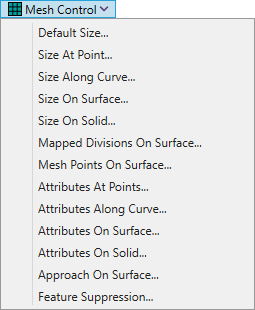
Default Size... - define the default element size. This default size is applied to all geometry instances where a specific size or number of elements has not been explicitly defined before.
Size at Point... - specifies the element size at a point.
Size along Curve... - specifies the quantity and distribution of elements along chosen curves.
Size on Surface... - set the mesh size along all curves that are used to define selected surfaces.
Size on Solid... - set the mesh size along all curves that are used to define selected solids.
Mapped Divisions on Surface... - allows you to specify divisions for a mesh on 3 and 4-sided surfaces.
Mesh Points on Surface... - opens or closes the Mesh Point Editor dockable panel.
Attributes at Point... - assigns meshing attributes (properties) to one or more points.
Attributes along Curve... - assigns meshing attributes to one or more curves.
Attributes on Surface... - assigns meshing attributes to one or more surfaces.
Attributes on Solid... - assigns meshing attributes to one or more solids.
Approach on Surface... - specify the type of mesh to be created on a surface.
Normally, without specifying an approach, will be decided whether to create a free/boundary mesh or a mapped mesh on each surface.
Feature Suppression... - allows the removal of features from the model during the meshing process.
Geometry
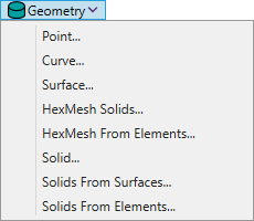
Point... - creates nodes (or elements and nodes) at the selected points.
Curve... - creates a mesh consisting of nodes and one-dimensional elements along a curve.
Surface... - creates nodes and planar elements on a selected set of surfaces.
HexMesh Solids... - creates a hexahedral mesh within a chosen set of solids.
HexMesh from Elements... - provides two methods to create a hex mesh out of mapped surface quads.
A hexahedral mesh can be generated either from a completely enclosed outer boundary consisting of mapped surface quadrilaterals or between a bottom and top mapped region connected by straight lines.
Solids... - creates a 3-D solid tetrahedral mesh in a solid part.
Solids from Surfaces... - produces a 3-D solid tetrahedral mesh in surfaces which enclose a volume.
Solids from Elements... - produces a 3-D solid tetrahedral mesh in planar elements enclosing a volume
Body
Bodies...
 - create a high-quality mesh by imposing fewer restrictions when meshing geometric surfaces (sheet solids), solids, and general bodies.
It can be utilized to generate a 2-D surface mesh on a connected sheet solid (stitched body), a general body, or a 3-D solid tetrahedral mesh within a solid part.
Mesh on Mesh...
 - create a high-quality mesh using existing triangular or quadrilateral elements as the starting point instead of geometric entities.
HexMesh Bodies...
 - creates high-quality elements that can be seamlessly transmitted to the Simcenter Nastran solver without requiring any further user intervention or manual mesh refinement.
Non-Geometry
Between...
 - creates a mapped mesh consisting of nodes and elements, aligning them between specified corner locations.
Region...
 - creates a ruled region comprising nodes and/or elements, connecting patterns of existing nodes.
Connect
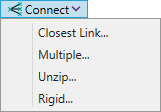
Closest Link... - from two sets of nodes automatically generates line elements, constraint equations, or rigid elements between each node in the first set of nodes (Generate From selection) to the nearest node in the second set of nodes (Generate To selection).
Multiple... - automatically generates line elements, constraint equations, or rigid elements between the source node and the destination node.
Unzip... - disconnect a mesh by creating new nodes. Afterwards, it links the nodes using constraint equations, rigid elements, DOF spring elements, spring elements, or gap elements.
Rigid... - automatically create rigid or interpolation elements.
Action
Editing
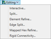
Interactive... - divide a singular linear or parabolic quadrilateral element into smaller quadrilaterals or triangles.
Split... - split multiple linear or parabolic quad elements into smaller quads or triangles.
Element Refine... - split selected elements according to selected pattern.
Edge Split... - split linear or parabolic elements by selecting two "corner" points.
Mapped Hex Refine... - split mapped hexahedral elements to create a finer hex mesh in a specific selected region.
Rigid Connectivity... - edit an existing rigid (RBE2) or interpolation (RBE3) elements.
Remesh
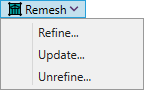
These commands are very similar. These commands take existing nodes and planar elements to generate a new mesh while maintaining the same boundaries.
Refine... - add additional nodes between later selected nodes.
Update... - same boundaries will be after nodes updated.
Unrefine... - automatically coarsen an existing mesh.
Edge/Skin Elements
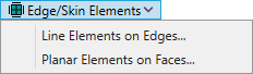
Line Elements on Edges... - creates line elements on edges of selected elements.
Plane Elements on Faces... - creates plane elements on faces of selected elements.
Extrude
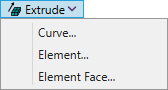
Curve... - creates planar elements with pre-defined mesh sizes along a vector, radially, along a curve, along element edges of a mapped mesh, or along a nodal path, using specified curves.
Element... - extrude elements by extending existing elements of a different type. Any line element or planar element is eligible for extrusion.
Element Face... - creates elements by extruding faces of existing elements.
Revolve
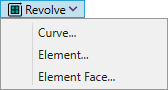
Curve... - creates planar elements by revolving curves around a specified vector - the axis of revolution.
Element... - creates planar or solid elements by revolving existing elements around a specified vector - the axis of revolution.
Element Face... - creates elements by revolving faces of existing elements.
Sweep
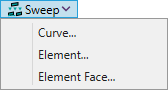
Curve... - sweep selected curves along one or more curves to form the new planar elements.
Element... - sweep selected elements along one or more curves to form the new planar(if 1-D elements are selected) or solid elements(if planar elements are selected).
Element Face... - sweep selected faces along one or more curves to form the new planar(if 1-D faces are selected) or solid elements(if planar faces are selected).
Copy
Entity
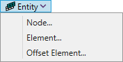
Node... - create one or more copies of a selected set of nodes along a specifed vector.
Element... - create one or more copies of a selected set of elements along a specifed vector.
Offset Element... - creates copies of the original entities(properties, constraints and regions). Use only for planar elements.
Radial
Node... - create copies of a selected set of nodes by using a single location (different radial vector for each entity to be copied) or a defined vector (entities to be copied are offset using a constant value from the vector), along with an offset distance.
Element... - create copies of a selected set of elements by using a single location (different radial vector for each entity to be copied) or a defined vector (entities to be copied are offset using a constant value from the vector), along with an offset distance.
Scale
Node... - create copies of a selected set of nodes by scaling a distance from original to specified coordinate location.
Element... - create copies of a selected set of elements by scaling a distance from original to specified coordinate location.
Rotate
Node... - create copies of a selected nodes with defined options by rotating them around specified vector.
Element... - create copies of a selected elements and associated nodes with defined options by rotating them around specified vector.
Reflect
Node... - create copies of a selected nodes with defined options by reflecting them across specified plane.
Element... - create copies of a selected elements and associated nodes with defined options by reflecting them across specified plane.
Modify
Project
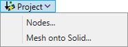
Nodes... - moves chosen nodes onto a selected curve or surface or onto a specified vector or plane.
Mesh onto Solid... - moves a mesh onto a solid or group of surfaces.
Move By
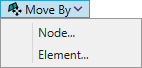
Node... - moves selected nodes along a specified vector.
Element... - moves selected elements along a specified vector.
Rotate By
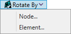
Node... - rotates selected nodes around a specified vector, a rotation angle and an optional translation distance can be defined or starting and ending locations.
Element... - rotates selected elements along a specified vector, a rotation angle and an optional translation distance can be defined or starting and ending locations.
Reflect
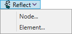
Node... - reflect selected nodes across a specified plane.
Element... - reflect selected elements across a specified plane.
Align
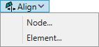
Node... - move selected nodes between specified vectors(from the first vector to the second), planes(from the first vector to the second), coordinate systems(from the first vector to the second).
Element... - move selected elements between specified vectors(from the first vector to the second), planes(from the first vector to the second), coordinate systems(from the first vector to the second).
Scale
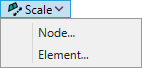
Node... - scale selected nodes around specified point with a defined scale factor.
Element... - scale selected elements around specified point with a defined scale factor.
Edit
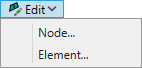
Node... - uses to redefine nodes.
Element... - uses to redefine elements.
Update Elements
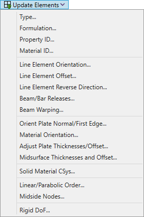
Type... - change type of selected elements by selecting property. Does not change type as a beam element to plate and vice versa.
Formulation... - specify the element formulation for a selected elements. All selected elements must be of the same type.
Property ID... - change a property for a selected set of elements.
Material ID... - change a material for a property which contains selected elements.
Line Element Orientation... - adjusts the orientation of different line elements.
Line Element Offset... - adjusts the offset of different line elements.
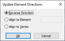
Line Element Reverse Direction... - allow to reverse line element's direction with 3 options to choose:
Beam/Bar Releases... - updates the releases for beam or bar elements.
Beam Warping... - updates warping of beam elements.
Orient Plate Normal/First Edge... - changes the default direction of chosen planar and solid elements.
Material Orientation... - modifies the material orientation angle for planar and axisymmetric elements.
Adjust Plate Thicknesses/Offset... - adjust the thickness or the offsets of the selected plate elements.
Midsurface Thicknesses and Offset... - update the element thickness and apply appropriate offsets to plate elements to better match the original solid used to create one or multiple midsurfaces.
Solid Material CSys... - override a material coordinate system to be specified for solid elements.
Linear/Parabolic Order... - changes linear elements to parabolic elements.
Midside Nodes... - moves nodes to the midpoint of element edges.
Rigid DoF... - change the Dependent and/or Independent degrees-of-freedom for existing rigid elements in your model.
Other
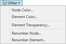
Node Color... - change color of selected set of nodes.
Element Color... - change color of selected set of elements.
Element Transparency... - change transparency of selected set of elements.
Renumber Node... - renumber IDs of selected set of nodes.
Renumber Element... - renumber IDs of selected set of elements.
Delete

These commands used to deleted selected nodes or elements and any model entities related to selected elements(Delete Mesh...).
Some entities could not be removed due to their necessity for another entities.