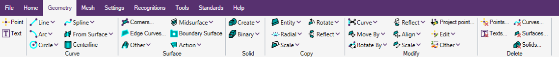
Geometry
Geometry serves as the foundation for the majority of finite element meshes. Hence, it is crucial to possess reliable tools for generating geometry.
SDC Verifier has the capability to construct geometry ranging from simple points to intricate 3-D solids. In essence, users can create, duplicate, or modify geometry.
Points
Points are used for constructing other geometry or finite element data.
 - Uses the coordinate definition dialog boxes to create points.
Text
 - Utilized for specifying text to annotate your model, which will be presented in the view.
Curve
Curves serve as the foundation for creating surfaces and can also be derived from surfaces.
These curves use reference points to establish their location. You can directly apply loads and constraints to curves, and they will be automatically converted into nodal/elemental values on the associated FEA entities.
Line
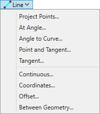
Project Points... - create a line between two locations.
At Angle... - create a line from specified base coordinates at a specified angle from the workplane X axis.
Angle to Curve... - create a line from specified base coordinates at a specified angle from the direction of specified curve.
Point and Tangent... - creates a line in the workplane through a point and tangent to a selected arc or circle.
Tangent... - creates a line in the workplane which is tangent to two arcs or circles.
Continuous... - creates a series of connected line segments between locations specified in three-dimensional space.
Coordinates... - creates a single line in three dimensional space between two specified coordinate locations.
Offset... - creates a line offset, in three dimensional space from another line.
Offset... - create a three-dimensional line by considering the minimum, maximum or both distances between two sets of chosen geometric entities..
Arc
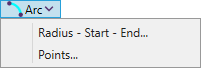
Radius-Start-End... - creates an arc in the workplane by specifying two end points and the desired radius.
You have the flexibility to define any three-dimensional locations, yet they will be projected onto the workplane along its normal direction.
Points... - creates an arc which passes through three locations on the perimeter.
Circle
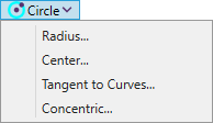
Radius... - creates a circle by defining the two endpoints of a radius, specifically, a point at the center and another on the circumference.
Centrer... - creates a circle in the workplane by specifying a location of the center and the length of the radius.
Tangent to Curves... - creates a circle of a specified radius in the workplane which is tangent to two other curves.
Concentric... - creates a circle in the workplane sharing the same center as another circle or arc. The new circle allows you to specify any desired radius.
Spline
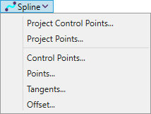
Project Control Points... - creates a spline in the workplane by the location of the control points. Specifying 4 points Bezier spline will be created, more points will force the curve to be a B-spline.
Project Points... - creates a spline in the workplane by the location of the points that spline passes through. The control points calculates automatically.
Specifying 4 points Bezier spline will be created, more points will force the curve to be a B-spline.
Control Points... - similar to Project Control Points... but control points are not projected on the workplane.
Points... - similar to Project Points... but points are not projected on the workplane.
Tangents... - creates a cubic Bezier spline by specifying starting and ending tangent vectors.
Offset... - creates a spline offset from another spline in a direction parallel to the workplane.
From Surface
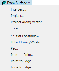
Intersect... - creates a curve at the points where surfaces of two solids intersect.
Project... - projects specified curves onto selected surfaces.
Project Along Vector... - projects specified curves onto selected surfaces along defined vector.
Slice... - create curves which will form the slice through the solid by defined plane.
Split at Locations... - create a parametric curve which by splitting selected face at defined locations.
Offset Curves/Washer... - has two modes Offset Curves and Washer.
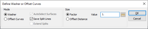
Washer should only be used for circular holes on planar surfaces.
Offset Curves is a more versatile mode suitable for creating oblong holes, slots, and various other shapes on a wide range of geometric surfaces.
Pad... - create a "pad" pattern around a hole by defining a circular edge on a surface.
Point to Point... - create a parametric curve along a surface by specifying a start point and an end point.
Point to Edge... - creates a parametric curve along a surface by defining a point and a curve on the same surface.
Edge to Edge... - creates parametric curves along a surface by choosing a single curve on a surface and then a choosing any number of curves also on that surface.
Centerline
 - attempts to create a curve which represents the centerline of a geometric solid.
Surface
Corners...
 - creates a surface by defining the location of three or four corners.
Edge Corners...
 - creates boundaries(series of connected curves that enclose an area ready to mesh).
Midsurface
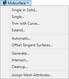
Single in Solid... - creates a single midsurface between two surfaces of a solid.
Single... - creates a single-sheet surface connecting two surfaces.
Trim with Curve... - trims/breaks a surface using a curve.
Extend... - extends a surface by employing one of its edge curves and extending the surface to a specified target location or distance.
Automatic... - attempts to employ face pairing technology within the Parasolid modeling engine to automatically generate a midsurface representation for a solid part or between chosen surfaces.
Offset Tangent Surfaces... - use on solids of constant thickness only.
Generate... - automatically creates all possible midsurfaces from selected surfaces.
Intersect... - automatically intersects or splits all chosen surfaces with each other.
Cleanup... - automatically identifies and assesses surfaces that can be deleted by examining for small, unattached surface components.
Assign Mesh Attributes... - automatically creates and assigns properties to selected midsurfaces based on the thickness of the solid from which they were created.
Boundary Surface
 - creates a surface by choosing three or four existing curves that delineate its boundaries or edges.
Other
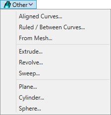
Aligned Curves... - create a standard geometry engine surface or a Parasolid surface.
Ruled/Between Curves... - creates a quadrilateral surface between two curves.
From Mesh... - creates a surface using any chosen number of selected shell elements.
Extrude... - creates surfaces by extruding one or more curves along a vector. Each selected curve results in a distinct ruled surface.
Revolve... - creates surfaces by revolving one or more curves through an angle around the vector.
Sweep... - create surfaces by moving or sweeping one or more curves along a path defined by a single curve.
Plane... - automatically creates a planar surface in a rectangular shape.
Cylinder... - creates surfaces which represent the curved lateral faces of a cylinder, cone or tube and optionally the planar endcaps.
Sphere... - creates a spherical surfaces.
Action
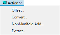
Offset... - creates a new surface by offsetting an existing surface.
Convert... - converts a boundary surface or a surface generated with the standard geometry engine to a Parasolid surface.
NonManifold Add... - create Non-Manifold Solid Geometry.
Extract... - extracts the chosen surface(s) from any solid, sheet solid, or general body where the surface(s) currently exist.
Solid
Create
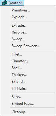
Primitives... - creates such geometry primitives as cylinders, blocks, cones and spheres.
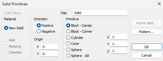
Set material, origin, direction to move solid, choose a primitive and define its parameters.
There are next types of primitives:
- Block-Center - create a block with an origin in the center. Define length of the edge of block in each direcion.
- Block-Corner - create a block with an origin in the corner. Define length of the edge of block in each direcion.
- Cylinder - create a cylinder. Define radius and height of the cylinder.
- Cone - create a cone. Define top radius, bottom radius and height of the cone.
- Sphere - create a sphere with eight 3-point surfaces. Define radius of the sphere.
- Sphere-Alt - create a sphere with six 4-point surfaces. Define radius of the sphere.
Solids are creating using patterns, it is possible to edit them by pressing .
Explode... - creates separate surfaces from a solid, eliminating the presence of the original solid.
Extrude... - moves a boundary or surface through a vector, and either create a new solid from the extrusion, remove material or add material.
Revolve... - revolves a boundary or surface around an axis of revolution, and either create a new solid from the extrusion, remove material or add material.
Sweep... - creates solids by moving or sweeping one or more boundary surfaces and/or surfaces along a continuous path defined by any number of curve.
Sweep Between... - creates a solid between two selected surfaces. A single point on each surface is also selected and used as a reference.
Fillet... - creates fillets on a solid model.
Chamfer... - creates chamfers on a solid model.
Shell... - used to “hollow out” a solid.
Thicken... - used to “thicken” or “thin out” (depending on the selected options) an existing solid using a component surface or surfaces or “thicken” a surface (sheet solid) into a solid by extruding in one specified normal direction or both.
Extend... - extend sa surface on a solid, sheet solid, or general body to a surface on another solid, sheet solid, or general body.
Fill Hole... - create a solid within an existing one by filling a void or hole.
Slice... - slice or create Cross Section from defined solid according to selected options.
Embed Face... - extend designated faces into new solid entities and integrate them into the original solid that enclosed those faces.
Cleanup... - check the solid, and remove any extraneous features which are not part of the actual solid.
Binary
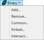
Add... - creates one solid from multiple, connected solids.
Remove... - substracts solids from defined solid.
Common... - creates a solid from the shared volumes between two solids.
Embed... - creates multiple solids: one from the shared volumes of each “embedded” solid and one from the remaining volume of the base solid.
Intersect... - automatically fractures surfaces on specified solids at their points of intersection.
Copy
Entity

Copy point, curves, surfaces and solid geometry along a defined vector.
Radial
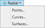
Copy entities to a single location (creates a different radial vector for each entity to be copied) or a defined vector (entities to be copied are offset using a constant value from the vector), along with an offset distance. Does not work with solid geometry.
Scale
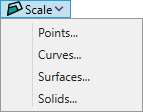
Copy entities by scaling the distance from the center to the original.
Rotate
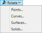
Rotate the duplicate copies around a vector using the specified options
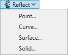
Reflect
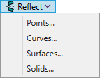
Reflect any portion of the model across a plane by flipping existing nodes or elements.
Modify
Curve
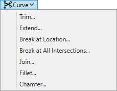
Trim... - trims curves at the points where they intersect with other curves.
Extend... - relocates the endpoints of one or multiple curves to a defined location.
Break at Location... - divides one or more curves into two segments at a specified location.
Break at All Intersections... - divides one or more curves into multiple segments, utilizing all identified intersections among the chosen curves.
Join... - connect two intersecting curves.
Fillet... - joins two curves with an arc of a defined radius.
Fillet... - cuts two intersecting lines at a defined distance from their endpoints, then links the trimmed ends with a new line.
Move By
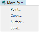
Move entities along the vector.
Rotate By
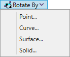
Rotate entities with a rotation vector, a rotation angle and an optional translation distance can be defined or starting and ending locations.
Reflect
Reflect the selected portion of the model across a plane by flipping existing points and other associated geometric entities
Align
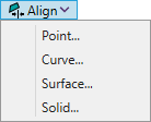
Provide a simple way of aligning portions of the model
Scale
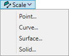
Change the size of your model entities.
Project Point...
 - adjusts the positions of points by relocating them onto a chosen curve, surface, or a specified vector or plane.
Edit
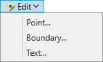
Redefine points, boundaries and text entities.
Other
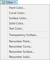
Commands to change color of model entities, transparency of surfaces and renumber model entities.
Delete
Commands to remove points, curves, surfaces, solids and text model entities.
Geometry
There are opportunity to create, modify, copy and remove solid geometry from geometry tree node.
Geometry contains all solid geometry. Solid`s visibility on the scene can be changed using entity visibility control.
Execute from the tree to add a new solid:
Set material, origin, direction to move solid, choose a primitive and define its parameters.
There are next types of primitives:
- Block-Center - create a block with an origin in the center. Define length of the edge of block in each direcion.
- Block-Corner - create a block with an origin in the corner. Define length of the edge of block in each direcion.
- Cylinder - create a cylinder. Define radius and height of the cylinder.
- Cone - create a cone. Define top radius, bottom radius and height of the cone.
- Sphere - create a sphere with eight 3-point surfaces. Define radius of the sphere.
- Sphere-Alt - create a sphere with six 4-point surfaces. Define radius of the sphere.
Solids are creating using patterns, it is possible to edit them by pressing .
Note: Eliminating the geometry also entails removing the mesh, properties, FEM loads, constraints, and so forth.