Tables
SDC Verifier implements tables single and multiple loads (Flow Tables).
- Expand/Extreme Table;
- Output Vector Expand/Extreme
- Flow Table (over loads);
- Summarized Forces (over nodes);
- Components Extreme (over selections);
- Modes Tables
Common Options
 - export the table to Excel.
 - copy the table to the clipboard.
 - open the Number Format Settings over result categories.
 - highlight selected node/element on the model automatically if turned ON.
 - display data in the table.
Expand/Extreme Table
An expand table displays the results for each Node or Element in Selection.
An extreme Table displays minimum, maximum, absolute maximum or max delta (for load groups) results and their location over directions.
To add Expand/Extreme Table execute from the tree.
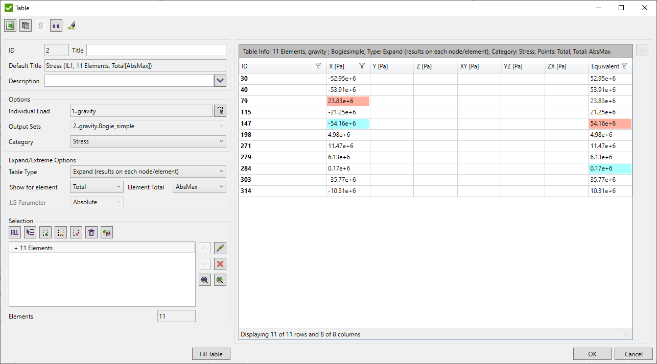
The following options for a table should be defined:
Load - select load using Load Selector Control;
Result Cases\Output Sets - a list of results, available only when a load contains few results.
Category - a result category to display the results for. Can be nodal (displacement etc.) or elemental (stress etc.)
Table Type - expand or extreme;
Expand settings - available when expand table type is selected:

Show for element - available for the element-nodal types of results.
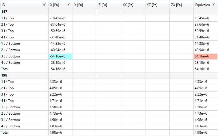
All Points - show top and bottom result for each corner node:
Total - show one value on element (calculated among all points);
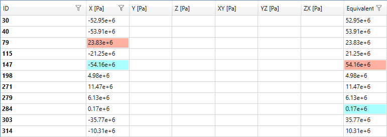
Element Total - available for element-nodal types of results. Defines the type of calculation of the total point: minimum, maximum, absolute maximum (AbsMax) or average among all points.
LG Parameter - available for Load Groups only. Defines the extreme type of result to be displayed on each node/element over the load group items.
Extreme settings - available when the extreme table type is selected:

Detailed - displays an entity Id where the worst result is found. For Load Groups also governing load is displayed:
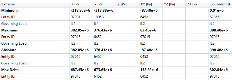
Short - displays only extreme values:

Selection can be defined using Selector Control. Selection Entity Type (Nodal or Elemental) depends on the table result category (displacement, stresses, etc.)
 - hide nodes with zero result for expand table (only for nodal results, can be used for displacement or reaction force tables).
 - display results that are multiplied on factors
of Individual Loads included in the selected Load Set. Table can be built for selected elements if Expand Table Type and
Load Set are set:
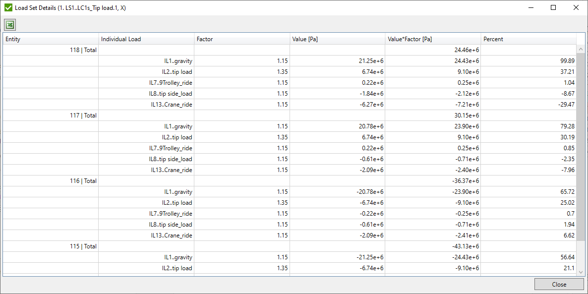
Common commands are described in the Common Options chapter.
Output Vector Expand/Extreme
An Output Vector table shows the result for each node/element from the selection for chosen Output vectors.
An Extreme Output Vector table shows the result min, max and absolute maximum for selection for chosen Output vectors.
The table can be created only for Individual Loads.
To add Output Vector Table execute from the tree:
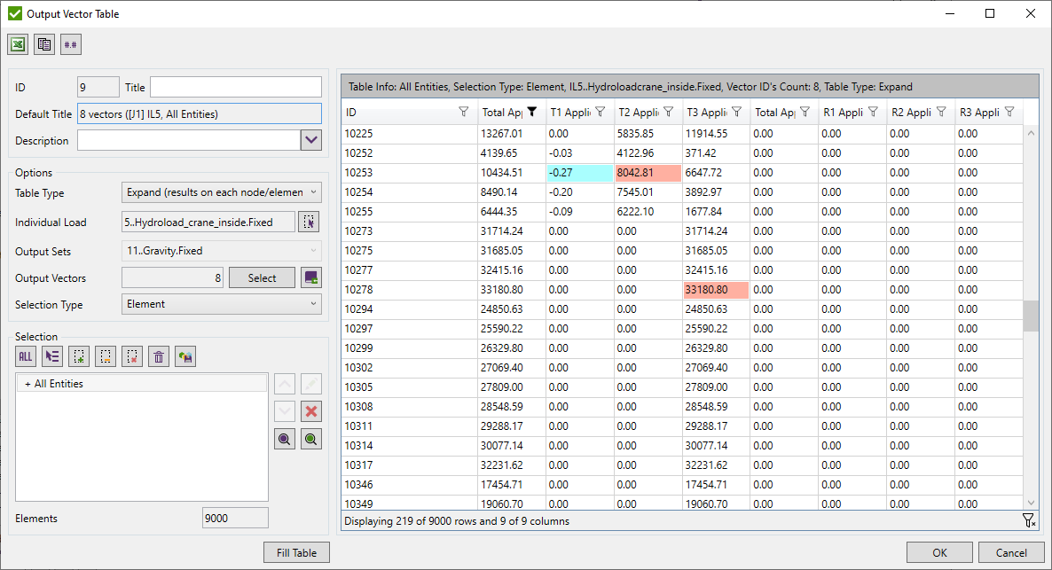
Output Extreme Vector Table:
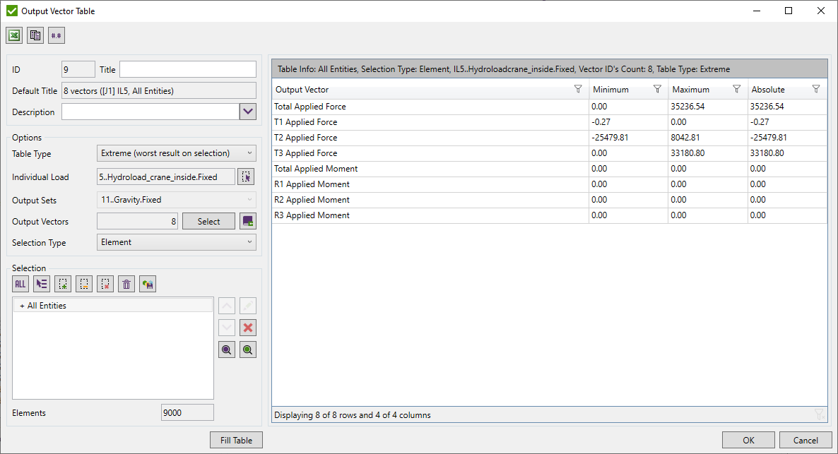
Select Table Type to choose between Output Vector and Extreme Output Vector table;
Select Load using Load Selector Control;
Select Output Vectors using Output Vectors Selector
Selection can be defined using Selector Control.
Common commands are described in the Common Options chapter.
Flow Table (over loads)
Flow table results are displayed for multiple loads at once. To add Flow Table execute from the tree.
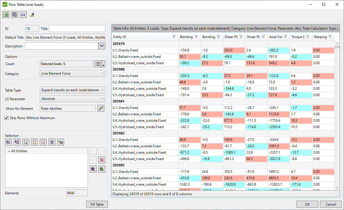
Select Loads using Multiple Load Selector Control
Category - result category to display results for. Can be nodal (displacement etc.) or elemental (stress etc.)
Table type - expand (detailed results for each node/element from the selection) or extreme (worst results on selection for each load);
Expand Options - available when expand table type is selected.

LG Parameter - defines the extreme type of result to be displayed on each node/element over load group items.
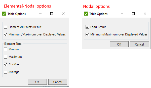
Show for Element/Node - for element-nodal types of results defines what points to display (all or total only), the type of calculation of the total point: minimum, maximum, absolute maximum (AbsMax) or average among all points. For nodal results - show results for loads or min/max result over all loads for one node:
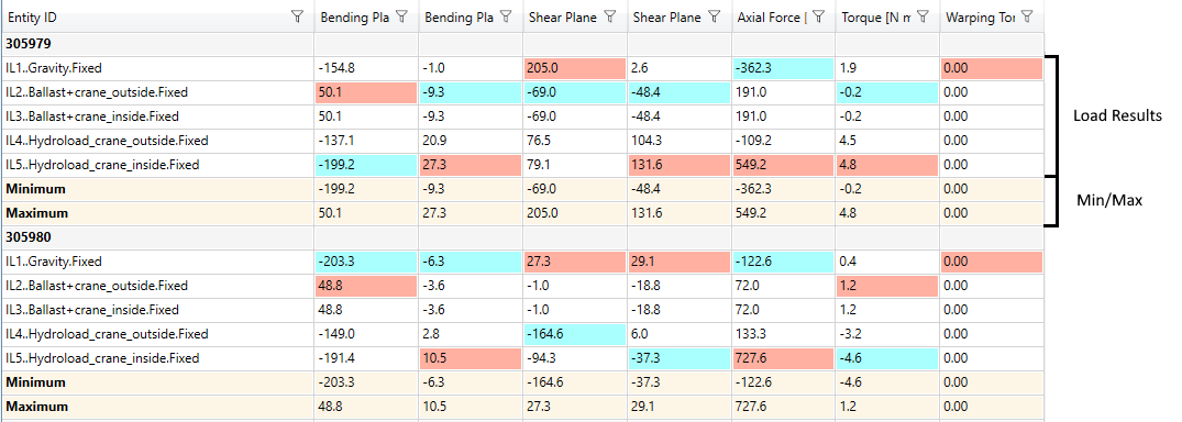
Skip Rows without maximum - do not display loads that do not cause any extreme for a single node/element. In the example table, IL3 and IL4 will be not displayed if this option is turned on:
Extreme Options - available when extreme table type is selected. Define the type of extreme to be displayed:

Selection can be defined using Selector Control.
Common commands are described in the Common Options chapter.
Summarized Forces (over nodes)
Summarized Forces (over nodes) table summarizes results for each selected selection and displays them for multiple loads at once.
To add the table execute from the tree:
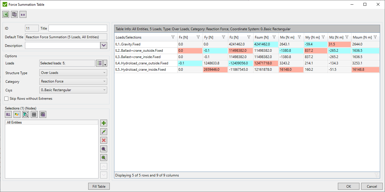
Select Loads using Multiple Load Selector Control:
Structure Type - defines the order of displayed results in the table. Over Loads - display each summarized result of all selected selections under each load. Over Selections - display summarized results of all selected loads under each selection;
Category - a result category to display results for. Can be nodal only (reaction forces, axial forces, etc.).
Csys - existing coordinate system created from the model to transform forces/moments into.
Skip Rows without Extremes - depending on the Structure Type, selections or loads that do not contain a minimum or maximum value in any direction withing the load/selection will not be displayed in the table;
Note: for load group, minimum and maximum summation will be found over its items.
Selections can be defined using Selection List Control.
Common commands are described in the Common Options chapter.
Components Extreme Table (over selections)
Display extreme results for multiple selections at once. To add Components Extreme Table execute from the tree.
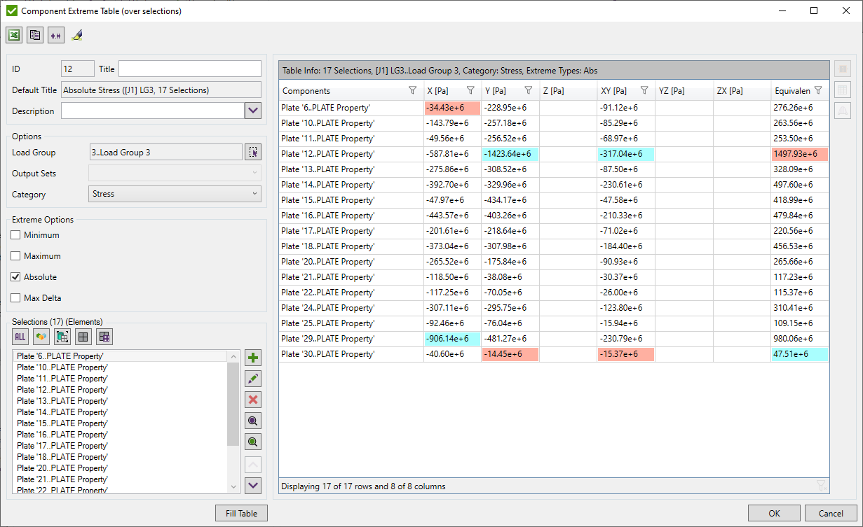
Load - select load using Load Selector Control;
Category - result category to display results for. Can be nodal only (reaction forces, displacement, etc.).
Extreme Options - minimum, maximum, absolute maximum and/or max delta (only for Load Groups) result will be displayed.
Selections can be defined using Selection List Control.
It is possible to plot labels of results. Press  to open the list of available directions for the selected category to the plot:
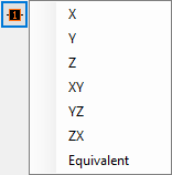
A criteria plot together with the labels of the maximum value on each selected selection will be displayed.
 - open Expand/Extreme Table
using selected selections from the table
Common commands are described in the Common Options chapter.
 - open Beam Member Diagram using selected selections from the table
Modes Tables
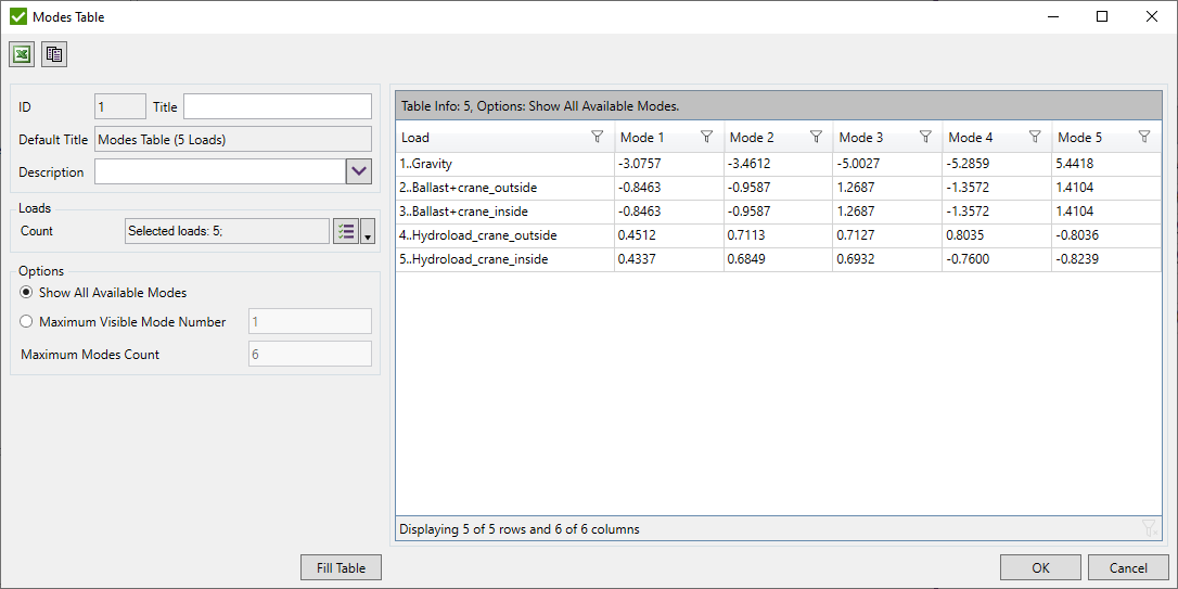
Modes table displays Eigen modes values for selected loads. To add Modes Tables execute from the tree.
It is possible to show all modes or define amount:
Common commands are described in the Common Options chapter.
