Plot Profiles
Plots – plot settings stored with a user-defined name.
SDC Verifier has 7 types of plots:
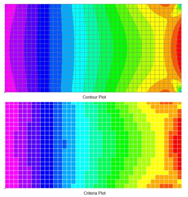
- Criteria – each element is colored based on a single output value for the element.
- Contour – element is colored based on the corner data. Typically is used for stresses and displacement plots.
- Output Vector Criteria – is the criteria plot but instead of selecting the result category and direction a user chooses an output vector that will be displayed.
- Output Vector Contour - is the contour plot but instead of selecting the result category and direction a user chooses an output vector that will be displayed.
- Histogram – is used for displaying extreme results on several loads at once.
- Expand Graph – similar to Histogram plot but instead of extreme results it displays node/element results on several loads at once.
- Beam Diagram – display results over beam members on several loads at once.
Common Options for criteria/contour plot profiles
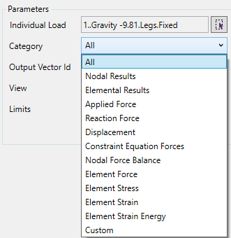
The first step is to define a load. Then, a category of the result should be selected (displacement, stresses, strains, etc.).
The direction parameter depends on the result category. For stress - direction of stresses (X, Y, ..., Equivalent), for forces - force and moment components, displacement - translation and rotation components, etc.
is enabled only for Load Groups.
Select Elements/Nodes using Selector Control.
The look of the plot depends on View Settings. It is possible to select a view from the list or add a new one.
Press  to display the plot.
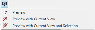
 display plot with all the settings;
 - display plot with current view settings (ignore view from plot options);
 - display plot with current view settings and current selection (ignore view and selection from plot options);
Press  to save the plot.
For Criteria/Contour plots use Labels Control to include labels with extreme values over recognition items (members, plates, stiffeners or welds), display min/max values of the model or show coordinates of sections from Panel Finder.
Add Criteria Plot
To Add Criteria Plot, right click node in the respective Job in the tree and select option:
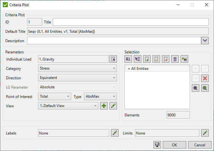
Common commands are described in Common Options chapter
For the elemental/nodal result category (e.g. stress) the point of interest and the type for total points has to be set.
Points of interests:
- End I/Top – among points 1-4.
- End J/Bottom = among points 5-8.
- Total – among all points.
By default, a calculation type is set to AbsMax (absolute maximum value among point values). There are 4 calculation types:
- Minimum.
- Maximum.
- AbsMax.
- Average.
Limits are described in Common Controls chapter
Add Contour Plot
To Add Contour Plot, right click node in the respective Job in the tree and select option:
For a contour plot, Data Conversion can be set. These options control how the results are converted from data at element centroids, corners and nodes to the continuous graphical representation.
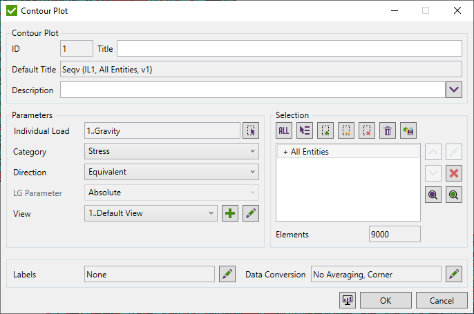
Common commands are described in Common Options chapter
Data Conversion is described in Common Controls chapter
Add Output Vector Plot
To Add Output Vector Criteria/Contour Plot, right click node in the respective Job in the tree and select option:
Output Vector plot is actually a Criteria plot, the only difference is that in the output vector instead of setting the result category and direction a user defines the output vector.
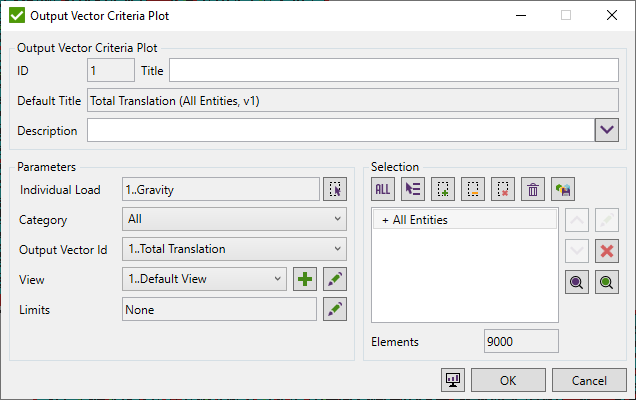
It is important to mention the filter for Output Vectors that helps to select the necessary output vector faster. By default, all vectors are displayed in the Output Vector list.
For the criteria plot, it is possible to set limits and for the contour plot - data conversion.
Histogram Plot
To Histogram Plot, right click node in the respective Job in the tree and select option:
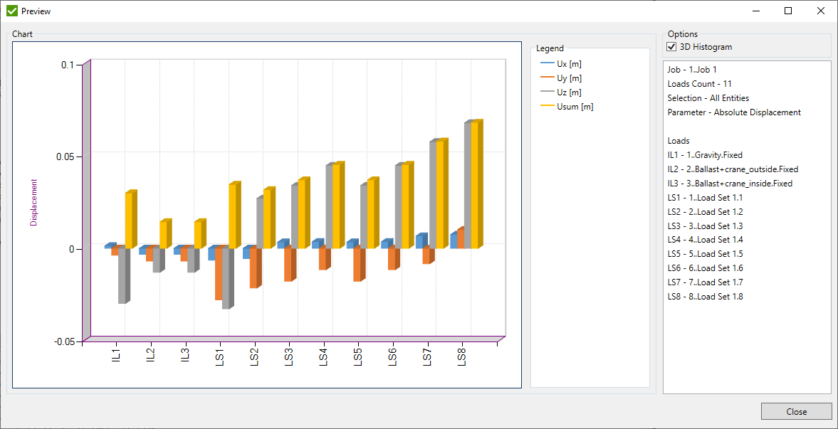
Histogram plot displays extreme results over directions for several loads at once.
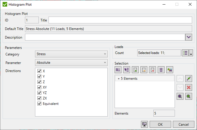
Select Loads using Load Selector.
When Loads are defined select the result category from the list.
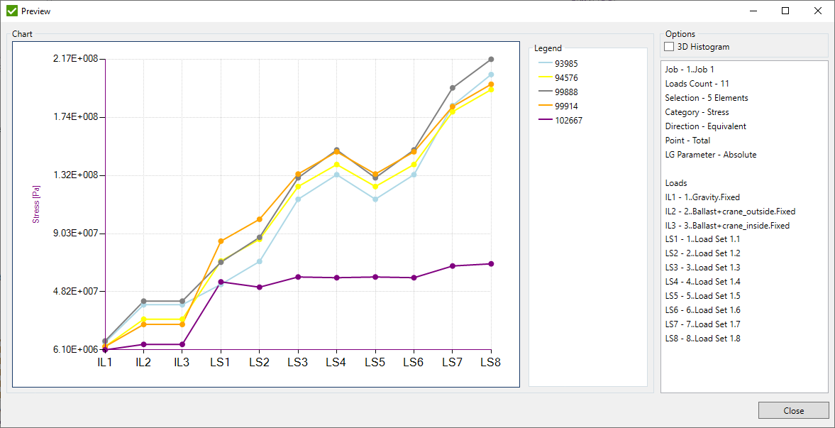
Expand Graph
To Expand Graph, right click node in the respective Job in the tree and select option:
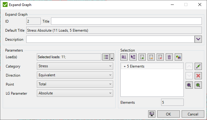
Expand Graph displays entity results for several loads at once. The graph is similar to Histogram but instead of the extreme results, it displays entity results.
When Loads are defined select the result Category, Direction, Point (only elemental results with Points) and Load Groups Parameter (Minimum, Maximum or Absolute).
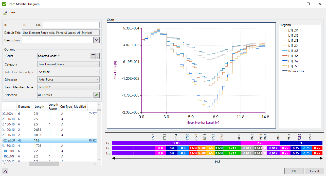
Beam Member Diagram
Beam Member Diagram - line element force results graph over beam members.
To Add Beam Member Diagram execute from the tree.
 - highlight selected node/element on the model automatically if turned ON.
 - show joints where beam member is split when turned ON.
Select Loads using Load Selector.
Category - type of result to be displayed;
Total Calculation Type - type of result among all the points of interest of the element. Available for Stress result category;
Direction - result direction;
Beam Members Type - show beam members from Y/Z/Torsional direction;
Selection - beam member is added in the table when all its elements are in the selection.