For the defense industry, a finite element analysis can produce thousands of results, but the key question remains:
Does the structure meet project requirements under the scenarios it must withstand?
This becomes especially important for extreme and non-standard loads. A stress contour alone does not identify the governing scenario, confirm the correct safety factors, or demonstrate compliancewith the defined verification criteria. Verification must connect the physical scenario to the result: from load cases and combinations to structural checks, governing results, and documented evidence.
This article outlines a practical approach to structural verification for defense, military, and naval engineering programs where exceptional operating scenarios, multiple configurations, and project-specific requirements can make load management, structural checking, and result traceability difficult to control.
Why Extreme Loads Are Difficult to Verify
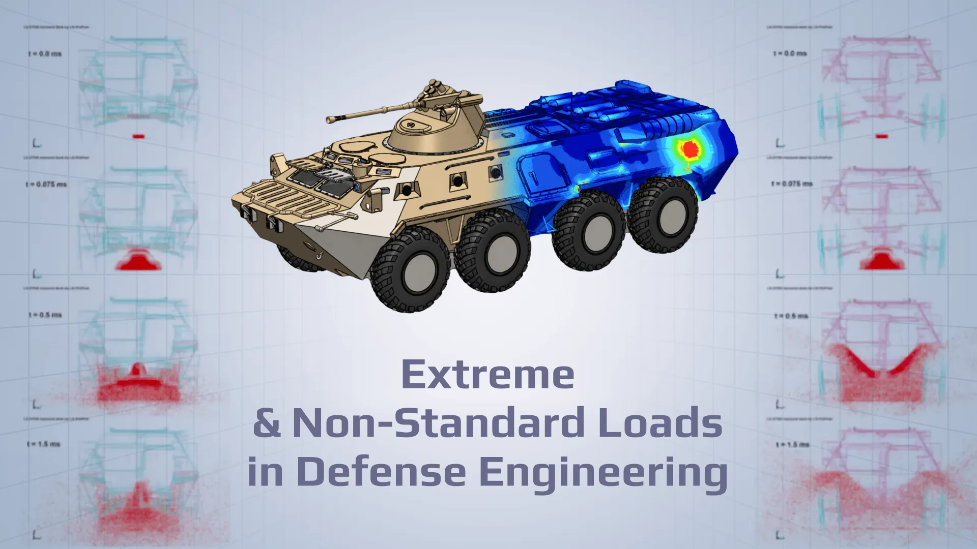
Verification of defense structures becomes more complex when the loading represents a specific event or operating condition. A structure may need to be assessed across multiple configurations, with asymmetric load paths, transient responses, or different combinations of loads and safety factors. The same platform can also have a long operational and modification history, creating an additional need to maintain consistent verification evidence between design iterations.
Typical examples of non-standard scenarios may include:
impact or transport events;
emergency manoeuvres;
transient acceleration;
uneven support conditions;
asymmetric loading;
exceptional operating states.
Image: Transient and asymmetric loads
These scenarios cannot always be represented by a single load case or analysis state. The engineering task is to define the relevant scenarios clearly enough that they can be analyzed and verified against the actual project basis.
This article is based on SDC Verifier’s webinar “Structural Compliance for Extreme and Non Standard Loads in Defense Industry”. See the full webinar here: https://youtu.be/XnSDL17Ocus?si=qnx_A8O3FDVbVMSx
Start with Scenarios, Not Result Envelopes
Before the analysis is run, the verification basis should define the physical scenario being evaluated, including the configuration, boundary conditions, loads, and acceptance criteria. This provides the context required to determine whether the correct model, loads, combinations, and acceptance criteria are being used.
For each relevant scenario, the verification basis should define:
the physical event or operating condition;
the structural configuration;
boundary conditions;
load direction and magnitude;
expected duration or response type;
acceptance criteria;
relevant structural details.
Image: Load-combination matrix with factors
Therefore, different scenarios may govern different parts of the same structure. The load case producing the model-wide maximum stress may not govern a local connection, plate panel, weld, or other structural detail.
Stresses and displacements are outputs of a simulation, but they do not independently establish whether the structure satisfies the applicable requirements. Model assumptions and load combinations must first correspond to what the structure is actually being evaluated against.
Build a Controlled Load-Combination Structure
Complex defense projects can involve many load cases, operating conditions, and safety-factor arrangements. Without a controlled structure for managing them, it becomes difficult to determine what each result represents and whether all required scenarios have been included.
For results from a linear analysis, load effects can be combined using factors when the assumptions required for linear superposition are satisfied.
Nonlinear and transient results require a different treatment. Nonlinear or transient result sets should normally remain associated with the analysis scenario that produced them rather than being factor-scaled as if they were linear load components.
A controlled load-combination structure should therefore preserve:
the individual scenario;
the source analysis;
the load sets involved;
the applicable factors;
the logic behind the combination.
Result envelopes can be useful for identifying critical regions. However, an envelope alone is not sufficient unless the governing result remains traceable to the load case or combination that produced it. Engineers still need to know which scenario produced the governing result and under what combination logic.
When combinations become numerous, maintaining this relationship between the scenario, factors, and resulting response becomes part of the verification process itself.
Verify Structural Items, Not Only Finite-Element Peaks
Finite-element stress are analysis results; they are not, by themselves, structural verification checks.
Verification frequently requires the model to be interpreted in terms of actual structural items and details. Depending on the project, this may include:
joints, connections, and local load-transfer zones;
bolts where relevant.
Structural recognition connects finite-element entities with the dimensions and structural details required by specific checks.
SDC Verifier includes recognition tools for structural entities and characteristics such as beam members, panels and plates, welds, joints, and connections from an FEA model. For these purposes, SDC Verifier offers Weld Finder, Beam Member Finder, Panel Finder, and Joints Finder tools. The resulting recognition data can then be used by applicable structural checks rather than requiring the engineer to evaluate only individual finite-element peaks.
For example, a local stress peak should not automatically be treated as the governing input for a plate buckling, weld strength, fatigue, or member check; each check uses its own required result treatment and structural data.
The objective is not simply to find the highest numerical value in the model. It is to evaluate the structural component against the criterion that applies to that component.
Identify the Governing Scenario for Each Critical Zone
A verification result becomes considerably more useful when it answers two questions at the same time:
Where is the critical region?
What caused it to govern?
Different parts of a structure may be controlled by different load cases or combinations. One region may be governed by an asymmetric operating condition, while another is controlled by a different configuration or loading scenario.
SDC Verifier’s Governing Loads tool can identify the critical loads within a Load Group and show which load governs elements or selected regions. Governing Loads can be evaluated for supported load results and check results.
Image: Governing-load plot
For each critical area, a useful verification result should therefore identify:
the location of the critical region;
the structural check that governs;
the load case or combination responsible;
the resulting utilization, damage, or margin;
the changes between design iterations.
This avoids reducing verification to a collection of disconnected maximum values. Instead, the engineer can trace a critical result back to the scenario that produced it.
That connection is particularly valuable during design changes. If a geometry, structural detail, or loading assumption changes, the governing scenario may change as well.
Use Custom Requirements Without Losing Consistency
Defense programs can combine recognized design standards with project- or customer-specific acceptance criteria.
The challenge is not only to define these additional requirements. They also need to be applied consistently throughout the verification process.
Project-specific criteria may involve additional formulae, factors, or checks that are not covered by the standard verification method selected for the analysis. Maintaining such requirements across separate spreadsheets can make updates and repeated verification more difficult to control.
Use custom checks as a way to define and automate company- or project-specific verification requirements. Applicable calculation methods can be implemented as defined custom checks and reused within the same verification environment.
Instead, where additional requirements are needed, they should be maintained as a defined verification method with clear inputs, formulae, and application logic. This helps avoid a situation where the same requirement is implemented differently across multiple spreadsheets or design iterations.
Keep Evidence Connected Through Design Changes
Structural verification rarely ends with the first model. Geometry changes. Loads are updated. Structural details are modified. New operating conditions may need to be assessed. Each change can affect both the numerical results and the scenario that governs the design.
The verification evidence should evolve with the model.
SDC Verifier’s Report Designer can generate structured reports containing model information, calculation results, plots, and tables. Report templates can include model information, materials, factors, assumptions, calculation results, and governing loads. After the model and verification results are updated, affected report content can be regenerated rather than recreated manually.
Image: A calculation report with the model basis, load scenarios, checks, and conclusion
This does not eliminate engineering review. It reduces repetitive manual post-processing and helps maintain consistency between the current analysis, verification results, and supporting documentation.
The result is a clearer calculation history that can be reviewed alongside the engineering model and its successive iterations.
How SDC Verifier Supports the Workflow
SDC Verifier can support this verification process as a post-processing, checking, and reporting layer within supported FEA workflows.
In practice SDC Verifier’s supports the workflow through the following capabilities:
working with FEA models and results in supported SDC Verifier workflows;
creating and managing load sets, load groups, and applicable linear combinations;
organizing analysis and verification results within the SDC Verifier project
recognizing structural items such as beams, plates, welds, and joints;
applying available engineering checks and defined custom checks;
identifying critical regions and governing load cases;
generating reports and updating their results after design changes.
Recognition tools connect FEA model entities with the structural information required for relevant verification checks. Load and result management helps organize multiple scenarios within the same project. Governing-result visualization can show which condition drives a critical response in different parts of the structure.
Custom checks provide a way to incorporate defined company- or project-specific calculation methods and verification criteria without treating them as disconnected calculations.
Reporting then connects the inputs, assumptions, factors, checks, and results into reviewable verification evidence.
From Simulation Results to Engineering Evidence
Extreme and non-standard loading conditions create a verification problem that cannot be solved by looking at the highest stress contour alone.
The central question is:
Which scenario governs? Which load combination and factors produced the result? Which structural item and criterion were checked? Does the result satisfy the defined requirement?
A practical verification process connects those questions in sequence:
Scenario → load case → combination → structural check → governing result → documented evidence.
That structure helps engineers move from a large set of FEA outputs to an understandable engineering conclusion.
For defense, military, and naval programs with multiple operating configurations, exceptional loading scenarios, project-specific criteria, and long design lifecycles, maintaining this connection can be as important as obtaining the simulation result itself.
A stress contour shows the response of a model. Structural verification must show the engineering basis behind the decision.