Rigid body elements are commonly used in finite element models to connect nodes, introduce loads, mass points, represent rigid connections, or transfer forces and moments between different parts of a structure. In Nastran, two of the most frequently used elements for this purpose are RBE2 and RBE3.
Although they are often discussed together, RBE2 and RBE3 do fundamentally different things. Choosing the wrong element can change the behavior of the FE model.
This article explains the difference between RBE2 and RBE3 elements in Nastran, how they affect stiffness and load transfer, when to use each one, and which modeling mistakes to avoid.
What Are RBE2 and RBE3 Elements in Nastran?
Rigid body elements, or RBEs, are used to define relationships between nodes without explicitly modeling a physical component such as a rigid bracket, coupling, or load introduction fixture.
Instead of creating detailed geometry for every connection, an RBE can establish a mathematical relationship between a reference node and a group of nodes in the FE model.
The important point is that not all RBEs impose the same relationship.
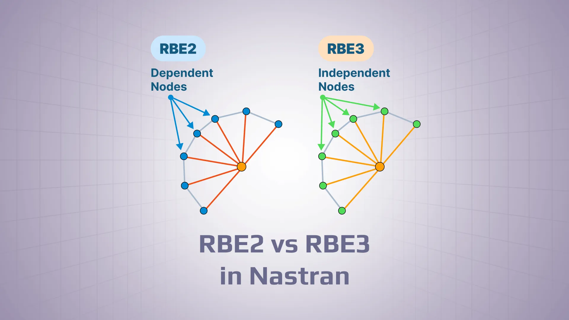
An RBE2 defines a kinematic constraint. The dependent nodes follow the motion of the independent node according to the selected degrees of freedom (DOFs).
An RBE3 is primarily a load-distribution element with beam releases that prevent rotations on connected nodes. It uses interpolation and weighting factors to distribute forces from a reference point.
RBE2: The Kinematic Rigid Coupling
An RBE2 element connects a group of dependent nodes to an independent or reference node. The selected DOFs of the dependent nodes are constrained to follow the motion of the independent node.
In practical terms, the connected region behaves as though it were rigid for the constrained DOFs.
For example, imagine a shell model with a circular group of nodes representing the attachment area of a rigid component. An RBE2 can connect those nodes to a central reference node. When the reference node moves or rotates, the connected nodes move according to the kinematic relationship defined by the RBE2.
This makes RBE2 useful for modeling genuinely rigid connections or components that can reasonably be considered rigid compared with the surrounding structure.
What does RBE2 do to stiffness?
RBE2 does not have a conventional material stiffness that you define with a Young’s modulus or thickness. Instead, its kinematic constraints prevent relative motion between the connected DOFs.
As a result, an RBE2 can make a region of the FE model behave much stiffer than the physical structure would.
This approach enables accounting for highly rigid components without explicitly modeling them, thereby reducing engineering effort.
The problem occurs when an RBE2 is used simply because it is a convenient way to connect nodes, while the real connection is flexible.
For example, replacing a flexible bracket or a compliant joint with an RBE2 can remove deformation that should be present in the model. The resulting load path and stress distribution may therefore differ significantly from the physical structure.
RBE3: The Interpolation Load Distributor
An RBE3 element serves a different purpose.
Rather than forcing the connected nodes to behave as a rigid body, RBE3 uses interpolation and weighting factors to distribute loads between a reference node and a set of independent nodes.
This makes RBE3 particularly useful for load introduction and load distribution.
Consider a force that physically acts over a relatively large area but is represented in the FE model by a single point. Applying that entire force directly to one node can create an unrealistic local load concentration.
An RBE3 can connect the reference point to multiple nodes and distribute the applied load across them.
It allows load or mass from a large connected component to be taken into account without the high stiffness effect characteristic of an RBE2.
RBE3 and stiffness
This is one of the most important differences between RBE2 and RBE3.
RBE3 is not intended to create a rigid connection between the reference node and the connected nodes. It distributes loads through interpolation rather than imposing the same kinematic constraints as RBE2.
Therefore, it is often preferred when the purpose of the connection is load distribution rather than forced stiffness increasing.
However, “RBE3 adds no stiffness” should not be interpreted as “RBE3 can never affect the results.” The selected nodes, DOFs, weighting factors, and overall model setup still influence how loads enter the structure.
RBE2 vs RBE3: What Is the Difference?
The simplest way to distinguish the two is to look at what they are designed to transfer.
RBE2
RBE3
Main purpose
Kinematic coupling
Load distribution
Basic behavior
Forces connected nodes to follow reference-node motion
Distributes loads using interpolation
Rigidizes connected region
Yes, for the constrained DOFs
No, not in the same kinematic sense
Can introduce artificial stiffness
Yes
Much less likely to do so through rigid-body constraints
Typical application
Rigid connection
Load introduction/distribution
Relative deformation of connected nodes
Restricted
Preserved
Uses weighting factors
No
Yes
Suitable for flexible load introduction
Generally not the first choice
Often appropriate
The difference becomes clearer when looking at a simple example. Suppose a force is applied to the center of a plate.
With an RBE2, the central reference node can be connected to a group of plate nodes. The connected region is constrained to follow the reference node’s motion. The plate area effectively behaves as a rigidized region.
With an RBE3, the force applied at the reference node can be distributed among the surrounding plate nodes while allowing the plate to deform.
Image: Difference between RBE2 and RBE3
So, although both elements can be used to connect a reference node to multiple FE nodes, they represent different physical assumptions.
How RBE2 and RBE3 Affect Stiffness and Load Transfer
The choice between RBE2 and RBE3 matters because it changes how the FE model transfers load.
RBE2 and artificial stiffness
When an RBE2 constrains multiple nodes to a reference node, it eliminates certain relative motions between those nodes.
If the real structure can deform in those directions, the RBE2 can make the model artificially stiff.
For this reason, an RBE2 should represent a physical assumption about rigidity rather than simply being used as a convenient connection tool.
RBE3 and load distribution
RBE3 is useful when the real structure can deform but the applied load needs to be distributed across several nodes.
For example, if a bracket transfers a force into a shell panel over a certain area, modeling the entire load through one node may produce an unrealistic local peak. An RBE3 can provide a more representative load introduction while allowing the surrounding panel to deform.
This makes RBE3 particularly useful for large shell models, where loads often need to be transferred from idealized points into distributed structural regions.
When Should You Use RBE2 vs RBE3?
The decision should start with the physical behavior you want the FE model to represent.
When to Use RBE2
Use RBE2 when the connected nodes should behave as a rigid body for the selected DOFs.
Typical examples include:
A rigid attachment point
A rigid bracket or fixture
A connection to a component that is much stiffer than the surrounding structure
A rigid interface between different parts of an FE model
A reference point representing a physically rigid component
For example, if a rigid actuator attachment is connected to several shell nodes and the attachment itself can reasonably be assumed not to deform, an RBE2 can be an appropriate representation.
When to Use RBE3
Use RBE3 when the main purpose is to distribute forces or weight/mass while retaining the flexibility of the connected structure.
Typical examples include:
Applying a point load over a shell surface
Distributing an applied force across several nodes
Introducing a moment into a flexible structure
Connecting a reference point to a flexible component
Representing a load transfer area without rigidizing the surrounding structure
A useful rule of thumb is:
RBE2 controls motion. RBE3 distributes load or mass.
It is not a replacement for understanding the physical connection, but it is a useful starting point when deciding which element to investigate.
RBE2 and RBE3 in SDC Verifier Workflow
SDC Verifiersupports both RBE2 and RBE3 elements in its standalone FEA environment. Engineers can create RBE2 connections using the Spider Nodes tool, work with existing rigid and interpolation elements, and modify RBE definitions when the modeling approach needs to change.
One of the available RBE Tools is Convert RBE2s to RBE3s. It modifies selected RBE2 elements into RBE3 elements, which can be useful when a connection initially modeled as rigid needs to be changed to a load-distributing connection.
SDC Verifier also includes a built-in Simcenter Nastran solver, allowing engineers to run the Nastran analysis directly in the software. This makes it possible to assess how different RBE definitions affect deformation, stress distribution, and load transfer as part of the same structural verification workflow.
Common RBE2 and RBE3 Modeling Mistakes
The element itself is rarely the only thing that determines whether the model is correct. The selected nodes and DOFs are equally important.
Using RBE2 to distribute a load over a flexible structure
If a load needs to be distributed across a plate or shell while the structure remains flexible, an RBE2 can rigidize the load introduction area.An RBE3 may be more appropriate in this situation.
Assuming RBE3 is simply a “softer RBE2”
RBE3 is not an RBE2 with reduced stiffness.The two elements use different formulations and serve different purposes. RBE2 imposes kinematic relationships, while RBE3 uses interpolation to distribute loads.The choice should therefore be based on the intended physical behavior, not on how much stiffness you want to add.
Connecting too many DOFs
Both the independent and dependent DOFs matter.Constraining DOFs that should remain free can introduce unintended behavior into the model. Before creating an RBE, check which translations and rotations the real connection actually transfers.
Choosing the wrong node group
The nodes connected to an RBE should represent the physical region through which the load or constraint is transferred.Connecting nodes that are too far away, too few, or not physically related to the connection can create an unrealistic load path.
Ignoring local stresses around an RBE
Rigid elements can significantly change the local stress field around the connection.A high stress immediately adjacent to an RBE does not automatically indicate a physical stress concentration. It may partly reflect the idealization used to introduce the load.For detailed stress assessment, the RBE setup should therefore be considered when interpreting local results.
Creating overlapping rigid connections
Multiple RBEs that share nodes or overlap inappropriately can introduce unintended constraints.This can make the model unnecessarily stiff or even produce conflicting constraints.When several RBE elements are used around the same connection, check the complete constraint chain rather than evaluating each RBE in isolation.
Conclusion
RBE2 and RBE3 can look similar in an FE model because both can connect a reference node to a group of structural nodes. Their effects on the model, however, are fundamentally different.
The right choice therefore depends on the physical behavior being modeled. If the connection should behave rigidly, RBE2 may be appropriate. If the main requirement is to distribute a load while preserving structural flexibility, RBE3 is often the better representation.
In either case, the RBE should be treated as part of the FE model’s physical idealization—not simply as a convenient way to connect nodes. The selected nodes, DOFs, and resulting load path all need to make sense for the structure being analyzed.
FAQs
How do you create an RBE2 in Ansys?
The exact procedure depends on the Ansys environment and the type of Nastran export being used. In general, an RBE2 requires a reference or independent node, a group of dependent nodes, and the DOFs that should be coupled.
After creating the connection, check the exported Nastran model if the final analysis is performed with a Nastran solver.
What is an RBE3 element in Nastran?
RBE3 is a Nastran interpolation element used primarily to distribute forces and weight/mass between a reference node and a group of nodes. Unlike RBE2, it does not impose the same rigid kinematic relationship on the connected structure.
Does RBE2 add stiffness?
RBE2 does not add material stiffness in the conventional sense. Instead, it imposes kinematic constraints between nodes. These constraints can make the connected region behave rigidly and therefore increase the effective stiffness of that part of the FE model.
Is RBE2 infinitely stiff?
RBE2 is often described as having infinite stiffness, but this is a simplification.
More precisely, RBE2 imposes kinematic constraints for the selected DOFs rather than assigning the connection a finite stiffness value. Relative motion that violates those constraints is not permitted.
Does RBE3 add stiffness?
RBE3 is not intended to rigidize the connected region. It distributes loads through interpolation while allowing the connected structure to retain its flexibility.
However, the way an RBE3 is defined can still affect the FE results, so its node selection, DOFs, and weighting factors should be checked.
Can RBE2 and RBE3 be used together?
Yes. Different parts of the same FE model may require different types of connections.
For example, an RBE2 can represent a genuinely rigid attachment, while an RBE3 can distribute a load into a flexible shell structure elsewhere in the model.
The important point is that each element should represent the physical behavior of the corresponding connection.