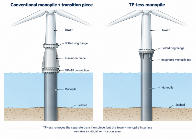
In a conventional offshore wind monopile foundation, a transition piece (TP) connects the monopile to the turbine tower. A transition-piece-less (TP-less) design removes this component and connects the tower directly to a flange at the top of the monopile.
This design is already being used in commercial projects. At OranjeWind, 53 TP-less monopiles are being installed. The turbine towers will be bolted directly to the monopile top flanges, while secondary-steel components are mounted in a separate installation campaign.
Removing the transition piece eliminates one major structural component and its connection to the monopile. However, engineers still need to verify the tower connection, the surrounding shell, and nearby welded details.
This article explains what changes, which FE results engineers need, and how SDC Verifier supports shell buckling, weld fatigue, and static bolt resistance checks.
Turn FE Results into Standards-Based Verification
Use SDC Verifier to check structural components against supported engineering standards, identify governing results across load cases, and document your calculations.
The tower-base bolted connection remains. What changes is the structure supporting its lower flange.
Component
Conventional monopile
TP-less monopile
Tower-base flange
Located on the transition piece
Integrated with the monopile top
Monopile–TP connection
Required
Eliminated
Secondary steel
Commonly attached to the TP
Integrated with or attached to the monopile
Tower interface during pile driving
TP installed after piling
Monopile top flange is present during piling
Three areas deserve attention during structural verification.
Monopile top. The tower flange, flange-to-shell welds, and nearby thickness transitions are part of the monopile. The FE model must represent these details sufficiently for the required checks.
Welded attachments. Access platforms, boat landings, and other secondary-steel components may introduce fatigue-sensitive connections directly into the monopile shell.
Installation effects. The permanent tower interface is exposed to handling and pile installation. Depending on the design basis, the assessment may need to consider installation loads, fatigue damage, and measured flange geometry.
These are not entirely new engineering problems. The TP-less arrangement changes where the relevant details are located and what the structural model needs to represent.
Start with the Right FE Model and Results
A standards-based check is only as reliable as the structural results used for it.
For offshore wind foundations, a global analysis determines the overall response of the tower and foundation under the required design loads. Local shell or connection models may then be needed where a simplified model cannot provide the stresses or forces required for verification.
For example, a global beam model may describe overall bending behaviour but not the contact and local bolt-force distribution in a tower-base ring flange.
The level of detail depends on the required check.
Verification
FE results and inputs needed
Shell buckling
Shell stresses, applicable load cases, panel geometry, material properties, and lateral pressure where relevant
Weld fatigue
Weld-related stress results, fatigue load cases and cycle counts, S–N curves, thickness, and environment
Bolt resistance
Bolt axial and shear forces from a suitable connection model, plus bolt geometry and connection parameters
SDC Verifier uses these results and model data to perform supported standards calculations. It cannot compensate for important connection behaviour or local effects that have not been represented adequately in the underlying analysis.
Monopiles are large cylindrical shells that can be subject to compression, bending, shear, and lateral pressure.
Near the tower interface, flange geometry, thickness changes, and local structural details can influence the stress distribution. The engineer must determine whether the selected shell-buckling method is applicable to the geometry and loading being checked.
How SDC Verifier helps
SDC Verifier implements DNV-RP-C202 (2019) for curved panels and unstiffened circular cylinders, covering Sections 3.1–3.4 of the standard.
With Panel Finder, engineers can recognize curved panels in the FE model and extract geometric parameters such as panel dimensions, thickness, and curvature.
SDC Verifier then uses the relevant FE stresses and standard parameters to calculate buckling utilization factors.
The workflow allows engineers to:
Identify the applicable curved shell regions.
Review recognized panel geometry and material properties.
Configure the DNV-RP-C202 check and its stress-evaluation settings.
Calculate utilization factors across selected load cases.
Identify governing regions and review detailed results.
For a monopile, particular care is needed when defining the checked shell region.
Panel boundaries, stress averaging, local discontinuities, and support conditions must be consistent with the physical structure and the assumptions of the selected buckling formulation.
A curved-panel check should not automatically be treated as complete verification of a shell containing significant openings, stiffeners, or local flange effects.
The benefit: engineers can perform repeatable DNV-RP-C202 checks on supported shell regions, review utilization results, and include those calculations in the verification report.
2. Weld Fatigue Verification with DNV-RP-C203
Offshore wind foundations experience repeated loading throughout their operating life. Fatigue assessment is therefore important for welded structural details.
For TP-less monopiles, relevant locations may include flange-to-shell welds, circumferential butt welds, thickness transitions, and secondary-steel attachments.
The fatigue assessment requires suitable stress results, loading information, and an applicable fatigue classification.
How SDC Verifier helps
SDC Verifier supports DNV-RP-C203 (2024) fatigue verification using the documented Method B stress-extraction approach.
The Weld Finder tool recognizes welds in a suitably prepared FE model and transforms element stresses into directions parallel and perpendicular to the weld.
This helps engineers work with weld-oriented stresses without manually reorienting the FE mesh.
A typical workflow includes:
Recognize and review the welded details.
Assign the applicable S–N curves and fatigue parameters.
Select the environment and thickness-related settings.
Define fatigue loading using Fatigue Groups and assigned cycle counts.
Calculate fatigue damage and review governing locations.
For supported configurations, SDC Verifier uses Method B stress read-out locations relative to the weld intersection or weld toe.
The documented implementation covers air and seawater with cathodic protection. Other environmental assumptions or fatigue requirements must be checked against the implemented functionality and project design basis.
The engineer remains responsible for selecting the correct fatigue classification and stress-assessment method. Fabrication effects such as weld misalignment must also be considered where required by the applicable methodology.
The benefit: SDC Verifier helps engineers recognize welded details, apply consistent fatigue settings, calculate damage across defined loading conditions, and identify the governing locations.
3. Bolt Resistance Checks with EN 1993-1-8
In a TP-less foundation, the tower is connected directly to the monopile through a bolted ring flange.
This connection transfers axial forces, bending moments, shear, and torsion. Individual bolt forces depend on the connection geometry, flange stiffness, preload, and load-transfer behaviour.
The bolt action effects must therefore come from a structural model appropriate for the connection being assessed.
The supported verification includes applicable checks for:
Bolt tension resistance.
Bolt shear resistance.
Bearing resistance.
Combined tension and shear.
Slip resistance.
The software obtains the relevant forces from supported bolt-type FE elements and applies the defined resistance equations using the configured bolt and connection properties.
Engineers can review individual bolt utilization factors and governing load cases without manually exporting every bolt force into separate spreadsheets.
However, a passing Eurocode bolt check does not establish that the complete tower–monopile flange has been verified.
The resistance check does not independently determine flange opening, contact-pressure distribution, nonlinear load redistribution, or the complete ring’s slip behaviour.
These effects must be addressed by the connection-analysis methodology where relevant. Preload and prying effects also need to be treated consistently when transferring FE results into the code check.
Static bolt resistance is separate from bolt fatigue. Where fatigue verification is required, engineers need an appropriate fatigue methodology and the relevant cyclic bolt-force information.
The implemented 2005 Eurocode edition must also be checked against the project’s specified standard edition.
The benefit: SDC Verifier automates supported static bolt resistance checks using suitable FE results, including evaluation across multiple load cases and detailed reporting of governing results.
4. Reviewing Results and Generating Verification Reports
Structural verification does not end when an individual check passes.
Engineers may need to evaluate many load cases, identify governing components, compare design revisions, and document the calculations for review.
How SDC Verifier helps
SDC Verifier provides results in tables and visual plots, including utilization results and criteria plots.
Engineers can identify governing components and load cases, inspect calculation details, and investigate regions that require closer attention.
Report Designer allows the verification results to be organized into engineering reports containing selected model information, calculations, tables, and plots.
When a model, load case, or verification setting changes, the affected checks can be recalculated and relevant report sections regenerated.
For projects involving multiple foundation variants or design revisions, this reduces repeated preparation of calculation documents while keeping the verification settings and results available for review.
Apply supported buckling, fatigue, and bolt checks to your FE results. Review governing utilizations, trace calculation details, and prepare engineering reports for review.
Removing the transition piece changes the structural arrangement of an offshore wind monopile foundation. The main verification tasks remain familiar: shell buckling, welded-detail fatigue, and bolted connection checks.
What matters is using structural models and results that adequately represent the relevant components.
SDC Verifier supports engineers by applying documented DNV and Eurocode calculations to suitable FE results, identifying governing checks, and organizing results into engineering reports.
It does not replace the detailed structural assessment of the tower–monopile interface. It helps engineers perform and document the verification checks that fall within its supported scope.