Most structural models require supports or boundary conditions to define structural behavior. In structural analysis, however, a support is represented as an idealized boundary condition that defines how the structure interacts with its surroundings.The selected support type determines which degrees of freedom are restrained, which reactions can develop, and how loads travel through the structural system. These assumptions directly influence reaction forces, bending moments, shear forces, deflection, and overall structural behavior.
In FEA, support conditions are implemented as boundary conditions that restrain specific translations or rotations. The main reason for using supports is to represent, as closely as possible, the real-life conditions that will exist in the modeled structure. Incorrect restraints can introduce artificial stiffness, permit rigid body motion, or distort reactions, stresses, deflections, and subsequent verification checks.
What Is Structural Support?
A structural support is used to represent how a modeled structure or component is connected to the surrounding system in real conditions. Supports define how loads, forces, and moments are transferred between the analyzed structure and the rest of the supporting structure, such as foundations, columns, bearings, walls, or frames. In an analytical model, supports provide the restraints required for equilibrium and define how applied loads are transferred into adjacent members, bearings, foundations, or other supporting components.
In structural analysis, support condition is modeled by restricting specific translations and/or rotations. In other words, support defines which movements are allowed and which are restrained under loading conditions. These restraint assumptions directly affect reaction forces, internal stresses, and bending moments.
A physical connection and its analytical support condition are not necessarily identical. A real connection or bearing rarely behaves as perfectly fixed, pinned, or roller support. These conditions are analytical idealizations selected to represent the required level of structural behavior.
A support defines three things:
Which movements are prevented;
Which reactions can develop;
How loads are transferred into the rest of the structure.
Why Support Conditions Matter in Structural Analysis
Support conditions directly influence how loads are transferred through a structure. The selected support type determines which reaction forces and moments can develop, and those reactions influence shear force, bending moment, axial force, torsion, and deflection throughout the model.
Even when geometry and loading remain identical, changing the support conditions can produce completely different structural behavior. A structure modeled with overly rigid supports may appear artificially stiff, while a model with insufficient restraint may show excessive displacement or unrealistic flexibility. If not enough degrees of freedom are restrained, the model can become unstable and experience rigid body motion. On the other hand, over-constraining a model can suppress realistic deformation and redistribute forces in a non-physical way.
This becomes especially important in FEA, where support conditions act as boundary conditions for the entire analysis. Incorrect restraints can create artificial stress peaks, distort buckling behavior, alter fatigue-critical locations, and affect serviceability results such as deflection.
Support symbols are useful in shorthand, but the governing question is which movements are restrained and which remain free. The applied load does not change, but the support reactions, bending moment distribution, and deflection shape change significantly because the restrained degrees of freedom are different in each case.
Support Reactions and Degrees of Freedom: The Basic Rule
Every support condition in structural analysis is fundamentally defined by degrees of freedom (DOFs). Instead of memorizing support symbols, you should think about which movements are restrained and which movements are allowed. Once the restrained degrees of freedom are known, the possible support reactions can also be determined.
In an idealized analytical model, a reaction can develop only in a restrained degree of freedom. If a translation or rotation is free, no corresponding reaction can develop in the idealized analytical model.
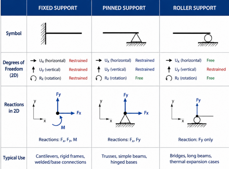
Image: Main support types diagram
Degrees of Freedom in a 2D Structural Model
In a typical 2D structural model, a node usually has three possible degrees of freedom:
Horizontal translation in the X direction
Vertical translation in the Y direction
Rotation about the out-of-plane axis, usually represented as (\theta_z). If this rotation is restrained, a reaction moment (M_z) can develop.
When a support restrains one or more of these movements, corresponding reaction components can develop.
Reaction
Meaning
Horizontal reaction
Resists movement in the X direction
Vertical reaction
Resists movement in the Y direction
Moment reaction
Resists rotation
For example, a pinned support restrains horizontal and vertical movement but allows rotation, so it develops horizontal and vertical reactions without a moment reaction. A fixed support restrains all three degrees of freedom and therefore develops force and moment reactions.
Degrees of Freedom in 3D and FEA Models
In a 3D beam or shell model, a node may have three translational degrees of freedom, (U_X), (U_Y), and (U_Z), together with three rotational degrees of freedom, (R_X), (R_Y), and (R_Z). Standard solid elements generally use translational nodal degrees of freedom only; rotational restraint is represented through displacement constraints, coupling, contact, or the modeled connection geometry.
The way these restraints are handled also depends on the element type. Beam, shell, and solid elements do not always interpret rotational and translational constraints in the same way. For example, beam elements usually include rotational degrees of freedom directly, while solid elements often transfer rotational behavior indirectly through displacement compatibility.
This is why support definition in FEA requires careful engineering judgment. A “fully fixed” constraint can be appropriate when the surrounding structure provides sufficiently high restraint and stiffness. When that assumption is not justified, it may overestimate stiffness, increase local stresses, or distort load transfer. Overly rigid boundary conditions may artificially increase local stresses, suppress realistic deformation, or distort load transfer paths.
In real structural verification workflows, engineers do not evaluate support reactions in isolation. Boundary conditions influence the entire FEA model, including stresses, buckling behavior, fatigue response, load combinations, and deflections.
Types of Supports and Their Reactions in Structural Analysis
Table: Common Support Types and Reactions
Reaction components below refer to idealized 2D structural behavior. In 3D models, restrained directions and reactions must be defined explicitly.
Assuming zero moment when connection has partial rigidity
Roller and sliding support
Translation normal to the supporting surface
Translation along the surface and rotation
One normal reaction, (R_n)
Bridges, long beams, thermal expansion cases
Missing horizontal restraint elsewhere
Cable/ tension support
Compression along axial direction
Motion when slack; no resistance in compression
Axial tension only
Cables, hangers, suspension systems, tie-downs
Assuming compressive capacity or linear behavior; ignoring slackness can significantly distort structural response
Spring/elastic support
Partially restrains movement
Limited movement depending on stiffness
Force proportional to displacement
Soil/foundation flexibility, flexible mounts
Choosing unrealistic stiffness
Fixed Support
A fixed support is an idealization of a very stiff connection rather than absolute rigidity. In FEA, excessive use of fixed supports can artificially increase stiffness, reduce deflections, and redistribute bending moments unrealistically.
Roller and Sliding Supports
Roller and sliding supports restrain movement only in the direction normal to the contact surface while allowing tangential translation and rotation. They provide a single reaction force perpendicular to the surface.
Cable and Tension Supports
Cable and tension supports are uniaxial elements that resist only tension and become inactive in compression. They generate axial tensile force aligned with the cable direction.
Spring or Elastic Supports
Spring or elastic supports depend entirely on the selected stiffness values. Unrealistic stiffness assumptions can produce numerically precise but physically inaccurate results.
Guided Supports in 3D and FEA Models
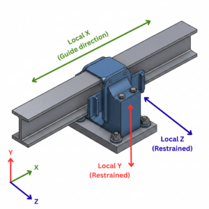
A guided support is best defined using local coordinates. For example, a pipe guide may allow axial movement along local X while restraining lateral movement in local Y and/or local Z. Depending on the physical detail, rotations may remain free or may also be restrained. Because of this, guided supports should be described by restrained degrees of freedom, not only by a 2D symbol.
Support type
Restrains
Allows
Reactions in 3D
Common use
Main modeling risk
Guided support
One or more translations perpendicular to the guide direction; rotations may optionally be restrained
Translation along guide axis; rotations may remain free depending on support detail
Reaction forces in restrained directions only; moment reactions only if rotational DOFs are restrained
Wrong local coordinate definition causing restraints in unintended directions
Image: 3D beam with guided support
Types of Beam Supports Commonly Used Together
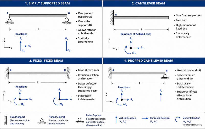
Beam behavior is defined not only by its geometry and loading, but also by how it is supported. In structural analysis, different combinations of support types form standard beam systems that directly influence stiffness, moment distribution, and deflection.
Image: Beam support combinations
Simply Supported Beam
A simply supported beam is typically modeled using one pin and one roller. In an idealized 2D model, this combination restrains the rigid body movements required for stability while allowing rotation and avoiding unnecessary axial restraint.
Support configuration:
One pinned support
One roller support
Behavior:
Stable system with free rotation at supports
No moment reaction at supports in idealized form
Typical use:
Hand calculations
Basic structural examples
Introductory beam theory
Cantilever Beam
A cantilever beam is fixed at one end and free at the other, creating a highly restrained boundary condition at the support.
Support configuration:
One fixed support
One free end
Behavior:
No support at the free end
Decreased deflection under load and length
Typical use:
Brackets
Overhangs
Structural arms and balconies
Fixed-Fixed Beam
A fixed-fixed beam is restrained against both translation and rotation at both ends, creating a highly stiff system.
Support configuration:
Two fixed supports
Behavior:
For the same beam geometry, material, span, and loading, a fixed-fixed model generally predicts lower deflection than a simply supported model, while introducing restraint moments at both ends.
High restraint moments at supports
Higher moment maximum value but zero moment at the end
Typical use:
Rigid frame members
Continuous welded beam systems
Engineering note:
Sensitive to settlement and thermal effects due to high restraint
Propped Cantilever Beam
A propped cantilever is typically modeled with a fixed restraint at one end and an additional vertical support near or at the other end.
Support configuration:
One fixed support
One pinned or roller support
Behavior:
Statically indeterminate system
Load sharing depends on stiffness distribution
Support reactions are not purely statically determined
Typical use:
Partial support of cantilevered structures
Retrofit or strengthened beam systems
Engineering note:
Support stiffness significantly influences internal force distribution
Continuous Beam
A continuous beam extends over more than two supports, creating multiple spans with shared load transfer.
Support configuration:
Three or more supports
Behavior:
Load redistribution between spans
Redistributes bending moments between spans and supports, often reducing positive span moments while introducing negative moments over intermediate supports.
Sensitive to continuity and stiffness distribution
Typical use:
Bridge girders
Multi-span floor systems
Engineering note:
Support settlement and stiffness variation can significantly alter moment diagrams
Overhanging Beam
An overhanging beam extends beyond one or more supports, creating cantilevered segments within a supported system.
Support configuration:
At least one span extends beyond the outer support
Behavior:
Depending on the applied loads and overhang length, significant negative moments can develop near the adjacent support.
Combined cantilever and simply supported behavior
Non-uniform moment distribution
Typical use:
Balcony slabs
Bridge end spans
Structural extensions
Engineering note:
Overhang length strongly influences local moment peaks and deflection behavior
Real Supports Are Not Always Ideal Supports
Real connections have finite stiffness. A connection represented as pinned, fixed, sliding, or elastic in a model should therefore be selected according to the behavior that matters for the analysis.
A welded connection is often assumed to behave close to a fixed support, but its real stiffness depends on weld size, geometry, plate thickness, and local flexibility of the connected members. Bolted connections may behave as nominally pinned, semi-rigid, or relatively stiff depending on the connection geometry, bolt arrangement, plate flexibility, slip behavior, preload where relevant, and the surrounding members.
Connection and support system effects:
Base plates, anchor bolts, grout layers, and foundation stiffness all contribute to overall restraint
Soil flexibility can significantly reduce effective fixity in foundation-supported structures
Bearing systems may be intentionally designed to allow rotation and controlled translation
Non-ideal physical behavior:
Friction may contribute to resistance, but it should not be relied upon as a stabilizing restraint unless that behavior is explicitly included and justified in the design model
Temperature effects can introduce additional forces and displacements in restrained systems
Settlement and fabrication tolerances can alter the intended load path
The drawing symbol is not the support behavior. The real behavior depends on connection stiffness, contact, geometry, anchorage, and the surrounding structure.
Support Conditions in FEA and Structural Verification
In finite element analysis, supports are implemented as boundary conditions that define which degrees of freedom are restrained at specific nodes or surfaces. These boundary conditions directly control how the model behaves under load and how internal forces are distributed throughout the structure.
A fully fixed boundary condition can introduce artificial stiffness or local stress concentrations when the real connection does not provide the assumed restraint. On the other hand, insufficient restraints may lead to rigid body motion or an unstable numerical model. At the same time, excessive or incorrectly placed supports can suppress realistic deformations and distort reaction forces and global load paths.
Verification results are only as reliable as the underlying structural model. Engineers therefore use support reactions together with stresses, displacements, internal forces, buckling response, fatigue results, and connection forces when assessing structural safety and serviceability.
SDC Verifier supports this workflow by using FEA results from SDC Verifier, Ansys Mechanical, Femap, and Simcenter 3D for standards-based verification and reporting. Apart from standalone, SDC Verifier has extensions SDC for Ansys, SDC for Femap, and SDC for Simcenter 3D.
Common Mistakes When Defining Supports
Incorrect support assumptions are a frequent source of misleading results in structural analysis and FEA. Even when loads, geometry, and material properties are correct, unrealistic boundary conditions can distort reactions, stresses, and deflections.
Common support modeling mistakes include:
Modeling every base connection as fully fixed without checking the actual stiffness of the connection, base plate, foundation, or soil
Using roller supports while forgetting to provide horizontal stability elsewhere in the structure
Confusing simple supports with pinned supports and assuming they behave identically
Restraining rotational degrees of freedom in shell or solid models without verifying whether the restraint is physically meaningful
Applying single-node restraint in a shell or solid model where the real support acts over an area, leading to non-physical constraint effects and artificial local stress concentrations.
Forgetting that local and global coordinate systems in FEA can change the direction of support restraints in models
Checking support reactions without verifying whether the foundation can actually carry those loads
Accepting reaction forces without checking sum of reactions to define whether it matches with loads.
How to Choose the Right Support Type for a Structural Model
Choosing the correct support condition starts with understanding how the real structure transfers load. The goal is not to select the “strongest” or most convenient support type, but to model the actual structural behavior as realistically as required for the analysis.
A practical approach is to work through the following steps:
Identify the real load path and determine where forces are transferred into the supporting structure
Decide which movements are physically restrained and which movements are free
Separate vertical, horizontal, and rotational restraint instead of treating a support as a single simplified condition
Evaluate whether the real connection behaves closer to pinned, fixed, sliding, or elastic behavior
Consider thermal expansion, settlement, contact conditions, and foundation or soil stiffness
Validate support reactions, deflections, and overall deformation against engineering expectations
Document all support assumptions clearly in the calculation package or verification report
Good support modeling is ultimately a balance between analytical simplicity and physical realism. A well-defined support condition should reflect how the structure actually behaves, not just how it appears in a drawing or schematic.
Summary Table: Which Support Type Should You Use?
Situation
Likely support model
Why
Beam resting on bearing with horizontal movement allowed
Roller/simple support
Allows expansion and rotation
Beam connected with ideal hinge
Pinned support
Resists forces, releases moment
Cantilever bracket welded to a stiff base
Fixed support
Rotation and translation restrained
Long bridge span with thermal movement
Pin + roller / bearing model
Stable but expansion-compatible
Machine frame on flexible mounts
Elastic/spring support
Support stiffness affects response
Cable hanger
Tension-only link/cable
Carries force along cable axis
FAQ
What are the main types of supports in structural analysis?
Fixed, pinned, roller, simple, sliding/guided, link/cable, and spring/elastic supports.
What reactions does a fixed support have?
Horizontal force, vertical force, and moment reaction in a 2D model.
What is the difference between pinned and fixed support?
Both can resist forces, but a pinned support allows rotation and does not resist moment; fixed support restrains rotation and develops moment.
What is the difference between pinned and roller support?
A pinned support resists horizontal and vertical movement; a roller support usually resists movement in only one direction and allows movement along the support surface.
What support types are used for a simply supported beam?
Usually one pinned support and one roller support.
Why do support conditions matter in FEA?
Because they define boundary conditions. Wrong supports can change reactions, stresses, deflections, buckling behavior, and verification results.
Are real supports perfectly pinned or fixed?
Rarely. Real connections often have partial stiffness, so the idealized support type should be chosen based on connection detail, stiffness, and engineering judgment.