A many-thousand-element model with multiple load cases may still allow some manual result extraction and reporting. You extract results, paste them into a spreadsheet, check the handful of plates that matter and rebuild the report when something changes.
The same manual approach is harder to sustain on a ship, tanker, or FPSO (floating production, storage and offloading unit) model with 500,000 to 1,000,000 elements. Add hundreds of load combinations, several applicable rule checks, and multiple design revisions, and the result-review, verification, and reporting workload grow rapidly.
The problem is not simply solver performance. It keeps geometry preparation, meshing, load management, structural recognition, verification, and reporting scalable throughout repeated design iterations. The following sections focus on making that verification workflow repeatable as models and requirements change.
Why large maritime FEA stops scaling
Model size is only the first multiplier. As the load matrix, code-check scope, and number of revisions grow, engineers must review more results, maintain more checks, and update more documentation.
Model size: A large maritime model can reach 500,000–1,000,000 elements. At this scale, geometry cleanup, mesh preparation, and result storage become more demanding.
Load count: A large maritime model may require hundreds of load combinations. Manually extracting and screening results for each combination becomes increasingly time-consuming.
Structural components: Instead of checking a few members by hand, engineers may need to verify the plate field, stiffeners, girders, and weld details included in the project’s verification scope. Identifying and dimensioning these components for each check adds further work.
Multiple standards: A project may require several classification society rules or customer requirements to be applied to the same model, creating parallel workflows and duplicated data.
Design revisions: Repeated scantling changes throughout design and approval mean that spreadsheets, plots, and tables must be updated and rebuilt after each revision.
Documentation: A short calculation note may be sufficient for a smaller model. A large maritime project, however, requires reports that trace each check to its corresponding load and structural location. Every design change can mean reassembling report chapters.
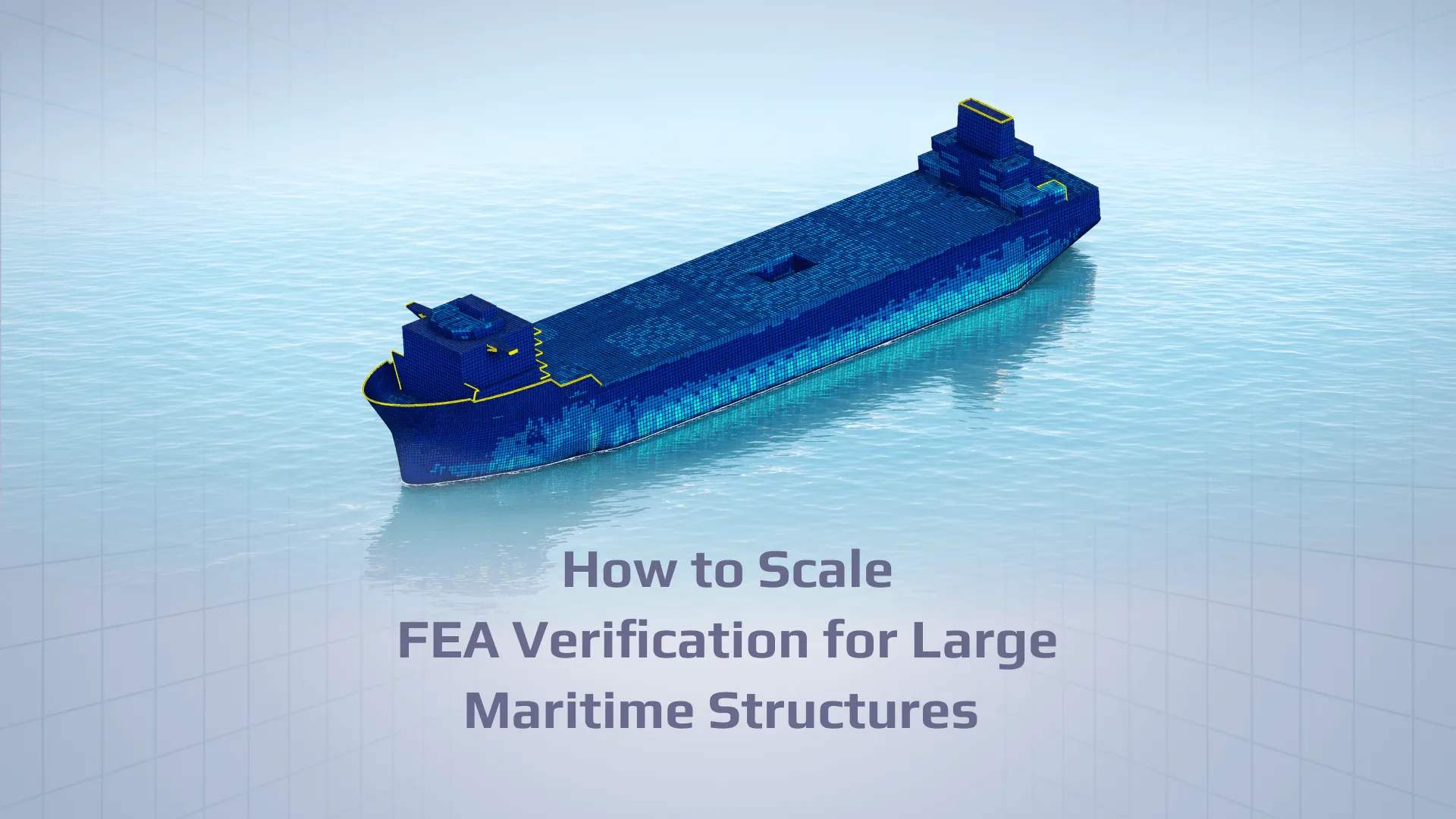
Image: Large maritime vessel FE model
This article is based on SDC Verifier’s webinar “Efficient approaches to FEA analysis of Large-Scale Maritime Assets: Ships, FPSOs, tankers”, see the webinar here –https://youtu.be/Vt8S6lPmVXU?si=bPFqxYEU1tne6r9f
Simplify the geometry without removing the structural behavior you need
A global shell model must preserve the stiffness, load paths, supports, and geometry needed for its intended loads and checks, but it does not need every small manufacturing detail from the CAD model. Simplify a feature when it does not change what the global model is asked to verify. Keep it, or move it to a local submodel, when it does.
Design CAD is built for manufacturing. It carries fillets, edge radii, drain holes, scallops, chamfers and cutouts, usually as solid or surface geometry. For a global model, that geometry is reduced to midsurfaces, with plate thickness assigned as a shell property. Every small feature left in at this stage constrains the mesh: it forces small elements and adds element count and solve time, often without changing the global response.
Image: Shell mesh
Geometry simplification is not indiscriminate deletion. Ask four questions of each feature:
Does it change stiffness or a load path?
Does it change a plate field dimension or a stiffener span used in a code check?
Is the stress around it part of the verification target, for example a fatigue-critical detail?
Do the applicable class rules require it to be represented in the global model?
Retain features that materially affect global stiffness, load paths, or applied loads in the global model. Details that primarily govern local stresses or fatigue may instead be assessed in a suitable local model with boundary conditions derived and checked against the global analysis.
Do not refine the entire model before you know where refinement matters
On a very large model, refining every region that might be critical before the first solve is expensive, and part of it is guesswork. A practical alternative is to start from a global mesh that already meets the applicable requirements, solve, and let the results show where refinement is needed.
The usual instinct is to predict hot spots in advance (openings, bracket toes, support regions, structural transitions) and refine all of them. On a model of half a million elements or more, each prediction adds elements, solve time and result storage. Some predictions turn out to be wrong, and the regions that do govern are not always the ones that were refined.
A staged approach:
Build a reasonably uniform global mesh that satisfies the analysis requirements and the mesh requirements of the applicable rules, such as element size tied to stiffener spacing where the rules prescribe it.
Solve the global model for the relevant load combinations.
Identify the governing regions from utilization, stress level and stress gradient.
Refine the regionsindicated by the results and any details for which the applicable check requires a finer mesh; rerun the relevant analysis.
This is one staged strategy, not a universal rule. It depends on the first mesh being valid for the checks it is used for. Where the applicable method prescribes a fine mesh from the outset, as in some hot-spot stress assessments, that requirement takes priority.
Convert the FE mesh into structural components
Many classification-rule checks require structural components such as plates, stiffened panels, stiffeners, girders, welds details to be identified and dimensioned from the FE model, rather than assessing isolated mesh elements alone. For large maritime models, identifying and measuring these components manually is time-consuming and must be repeated after geometry changes.
Each verification requires specific structural information:
Plate and stiffener buckling: Plate dimensions, thickness, orientation, and stresses in plate directions.
Weld strength and fatigue: Weld locations and connection geometry, together with the weld properties and stress inputs required by the selected strength or fatigue method..
Beam member checks: Member lengths between joints rather than individual element lengths. Recognized using Beam Member Finder.
SDC Verifier’s recognition tools derive these components from mesh connectivity and element properties. In the webinar demonstration, Panel Finder processed a model with roughly 500,000 elements in about one minute; actual performance depends on model complexity and settings.
Image: Half-million-element model with recognized sections
Using Panel Finder, you can identify sections, panels, plates, and stiffeners, and group stiffened panels and girders.
Weld Finderhelps identify weld connections represented in the FE mesh for subsequent strength and fatigue assessment.
Beam Member Finder allows you to identify beam members and define their lengths between joints for accurate beam strength and buckling checks.
However, recognition does not replace engineering review. Missing or unusually modeled stiffeners and girders can affect plate dimensions. Engineers should review recognized components and manually adjust them where necessary.
Once reviewed, component definitions can be reused across load combinations and rule sets. After a geometry or mesh update, engineers can rerun on update recognition and review the affected component definitions before recalculating the relevant checks.
Automate repetitive maritime loading where the physics permits it
FEA loads such as buoyancy, tank, wind and wave are tedious to apply by hand on a large hull and easy to get subtly wrong. Generate supported loads from parameters, check their element selections, directions, and equilibrium, and revisit those checks when the model or loading changes.
Image: Buoyancy/wave load setup
SDC Verifierprovides parameter-driven FEM loads for different model selections.
Buoyancy Load: Applies pressure to selected hull plate faces and forces to beam elements. It can also account for wave parameters and waterline equilibrium.
Tank Load: Applies pressure to selected tank plate elements.
Wind Load: Calculates loads based on the defined exposed geometry and wind coefficients.
Wave Load: Applies wave and current loading to beam, bar, and curved-beam elements.
For a linear analysis with unchanged stiffness and boundary conditions, solved base-load responses can be combined by superposition, avoiding a separate FE solve for each combination. If contact, geometric nonlinearity, or load-dependent supports affect the response; the relevant combinations may require separate nonlinear analyses.
Find governing load combinations before repeating expensive checks
With hundreds of combinations, the useful question is not “what is the maximum stress?” but “which combination governs which part of the structure?”. Reviewing every combination across a large model means hundreds of contour plots and tables.
The SDC Verifier’s Governing Loads toolidentifies the load cases that govern a specified result criterion within a selected load group and region. Engineers can use supported FE load results or calculated check results, apply filters, and review summary or element-level outputs. The governing case therefore depends on the selected result or checks criteria.
Image: Governing Loads plot showing critical load cases across a selected model region
In the webinar, the result was shown as a plot of the model colored by governing load, and the associated result values can be reviewed in the tool’s tables.
When governing-load reduction is valid — and when it is not
Static strength and buckling: governing cases should be determined using the stress component or code-check criterion relevant to the assessment. The case with the highest von Mises stress does not necessarily govern plate buckling, which may depend on normal and shear stresses acting together. Required combinations should not be omitted without a justified screening method.
Fatigue: for fatigue, all relevant cyclic load cases may still be required. Governing-load reduction is primarily useful where the verification method permits it, such as certain static-strength workflows.
Nonlinear response: if combinations cannot be obtained by superposition, each still needs its own solve. Governing-load screening then reduces post-processing, not solving.
Run multiple class-rule checks on one model
Maritime projects often require verification against more than one classification society’s rules. Depending on the vessel or offshore asset, its class notation, and contractual requirements, a project may combine checks from different applicable rule sets.
Running each assessment in a separate workflow means duplicating model data, managing different result sets, and increasing the risk of inconsistencies when the design changes.
SDC Verifier allows engineers to run multiple class-rule checks on the same FE model. The model and recognized structural components can be reused, while each rule set applies its own verification criteria. When the geometry changes, engineers can update the model and rerun the relevant checks without rebuilding separate verification models.
SDC Verifier includes specific implemented checks from several maritime and offshore rule sets. Examples relevant to different structural scopes include:
Using one FE model does not mean the rule sets produce the same results. Each classification society has its own safety factors, plate dimension conventions, and verification criteria. A structural component may pass under one standard and fail under another. Engineers must assess the results against the applicable project requirements and determine which criteria govern.
Make design iterations cheaper than the first calculation
The first full verification of a large model is expensive once. In a manual workflow, every revision is nearly as expensive again, and a maritime structure goes through many revisions between concept, class approval and construction.
Changing one plate thickness or one stiffener should not mean rebuilding by hand:
extracted results;
spreadsheets;
plots;
tables;
verification evidence;
report chapters.
Each output is linked to model data and verification settings. When a revision arrives, engineers determine whether the FE solution, loads, recognized components, or code checks are affected, update the necessary parts, and regenerate the relevant report content.
In SDC Verifier, the verification setup — load combinations, recognized components, checks and report template — is stored with the project. The engineering report is regenerated from the revised model rather than reassembled.
Design changes can also be evaluated before they are committed. The optimization module runs alternative thicknesses or sections against the same code checks, so a scantling trade study uses the verification logic instead of a separate estimate. Selected design changes still need an updated FE analysis and final verification where they affect the structural response.
What this looks like on real maritime projects
Shallow Draft Drilling System – ABS Verification
Image: Customer model checked against ABS standard
Cosimtec Pte Ltd used Femap/Simcenter Nastran and SDC Verifier for a Shallow Draft Drilling System (SDDS), a barge-based offshore application. The public case study describes more than 650,000 FE elements, eight complex load cases, ABS-related verification, buoyancy/tank-load application, Free Edge checks, plate buckling, and reporting.
The customer-reported reductions in this specific project were approximately 20–30% for overall project time, more than 60% for buckling checks, and more than 70% for report generation. These are project-specific estimates, not general performance guarantees.
LNG Bunkering Vessel – Structural Verification Under BV NR467
Image: Customer model checked against BV standard
CESAC used SDC for Femap to assess LNG tank saddle supports and the double-bottom structure of Spain’s first LNG bunkering vessel. The public project story describes Bureau Veritas NR467 checks under ULS and ALS conditions, including nonlinear GAP contact behavior, critical-zone refinement, redesign, and a documented review package.
This case illustrates an important boundary of automation: a global model, local refinement, nonlinear contacts, and class-oriented verification must be combined with engineering judgment. Code checks and automated reports accelerate the repeatable parts; they do not replace the analysis method or the class review.
A scalable maritime FEA workflow
Scaling maritime FEA requires reducing repetitive manual work at every stage, from geometry preparation to verification and reporting. A more efficient approach is to start with a consistent global model, identify critical areas, and focus detailed analysis where it is needed.
A typical workflow using SDC Verifier or its integrations with an FEA platform can look like this: 1. CAD and geometry preparation: Import the design geometry and simplify details only where they are not needed to represent the relevant global response, loads, or verification criteria.
Simplification and midsurfacing: Convert 3D plate structures into 2D surfaces, assign thickness and material properties, and prepare geometry for meshing.
Initial meshing: Generate an initial mesh that meets the applicable requirements without over-refining the entire structure.
Load application: Define load cases and combinations. Apply relevant loads, including buoyancy, wind, and wave loads where applicable.
FEA solve: Run the initial analysis to obtain stress and displacement results.
Identify governing regions and load cases: Use results and the Governing Load Tool to locate critical structural areas and identify governing cases for the selected FE result or supported code-check criterion.
Structural recognition:Use the appropriate recognition tools to identify relevant structural components and review their definitions before running the checks.
Code verification: Run the required buckling, fatigue, strength, and other checks against applicable classification rules using the same model.
Targeted refinement: Refine the mesh or structural details in critical areas rather than applying a uniformly fine mesh across the entire model.
Rerun and reassess: Update the analysis and relevant checks after design changes, focusing on governing regions and load cases where possible.
Automated reporting: Generate structured reports containing verification results, load combinations, boundary conditions, and traceable structural locations for class review.
Image: SDC Verifier’s workflow diagram
The objective is to spend less time preparing, repeating, and documenting calculations, and more time on engineering decisions, structural improvements, and design optimization.
Discuss your maritime verification workflow.
Request a technical demo to review how the approach could fit your model, loading conditions, and classification requirements.