Residual Life Analyses for Crane Structures. How to Avoid Cracks and Crane Fatigue

Why it is important to know your crane Design Life
Cranes, as well as other welded structures subjected to repetitive loading, are experiencing fatigue whenever they are working. The components of these structures have finite design life correlated with the usage cycle quantity and not with calendar time. Therefore, the structures’ design life is measured in work cycles, not running hours.
Crane Design Life is one of the crucial criteria of the economic aspect of owning and maintaining any lifting appliance or structure subjected to repetitive loading. Because the graph of expenses over a lifetime is not linear, and within a particular time, the costs of maintenance, upgrades, modifications, and inspections are rising due to the fixes’ necessity.
Regular reviews are sufficient to identify the risks and support compliance. But there is a high chance of missing some failures, and the price of later reviews will be too high. And the likelihood of such failures increases over time, which is the highest closer to the end of the design life.
So, knowing the remaining design life of the crane and its components gives an estimate of the limit for safe operational life. It is always based on actual usage, and knowing the design life of the crane allows planning timely modernization to extend the lifetime. If the upgrade is skipped at some point, operations will be possible, but with potential failures, and every minute or hour of downtime of lifting equipment is too expensive. Previously, it was common practice to change out structural components on a five-year cycle to ensure their integrity. Still, this maintenance process can take a couple of weeks, hampering or delaying work on the deck. It is better to think upfront.
Crucial criteria for proper Fatigue Analysis
Understanding structural fatigue in ship-to-shore cranes and their overall condition is vital in ensuring the integrity of deck operations and meeting safety requirements. A critical part of analyzing fatigue is determining an accurate life cycle. In most cases, gaining reliable information to choose the crane’s life cycle can be challenging.
Many of today’s cranes have a recording load indicator system with a complete history of each lift, detailing the weight and the position the trolley was in when this took place. This is ideal for fatigue analysis, but many aging cranes will not have this information, or if they do, it will only be available for a small proportion of the crane’s life. Here the modeling environments come to help. When talking about fatigue verification with the help of finite elements simulation, there are a few key points for appropriate analysis: a dedicated modeling approach, taking into account the usage cases and the distribution of the load over the structure, weld detection, and definition of weld types.
Building a dedicated FEA Model
Typically, engineers start with a simple beam model and build digital twins – a computer model of the structure to simulate the behaviour to apply all possible scenarios of loading to run the analysis. Usually, this is the beginning and the end of the analysis. Then they receive some utilization factor values or usage factors per all cross-sections of the structural member that just highlight peak zones in the model, which are very rough and not indicating the clear location of the problem and solution for it.
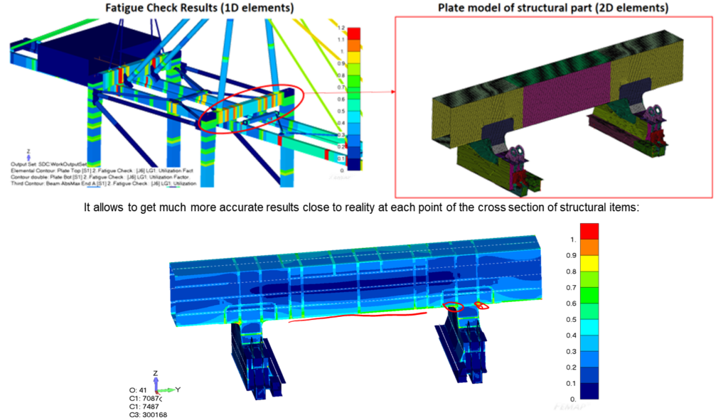
SDC Verifier implements the different approach, which is to build a very detailed model with shell or even solid elements in the locations that are subjected to some potential pain points. The analysis does not end at 1D model stage but continues to very detailed plate model with fine mesh. It allows getting very accurate results and obtain the correct results on welds because cracks due to fatigue are most likely to occur on welds. SDC Verifier has special tools to automatically detect welds on this kind of models and to indicate real points of damage and real results for welds. The engineer will not only have an approximate location of potential problems, but as a result of the checks fatigue damage on welds, the remaining amount of cycles to failure.
Often, in the simple models, bogie sets modelled as a stiff triangle to simulate the boundary conditions, but we’ve done an evaluation which proves that detailed model of the bogie set has a significant influence of on the stiffness of the structure. We always recommend modelling the bogie sets with the shell elements and as detailed as possible because sometimes it’s up to 25% difference in the stiffness results.
Taking into account use cases and load distributions
Another one crucial criterion for proper fatigue analysis is building a correct workload distribution over the structure. Except of gravity load, gantry load, wind (storm) loads, cranes have some travelling/hoisting or lifting load – a trolley or a grab. It is essential to determine detailed amount of positions of this load, each place where the spreader is connected to the container where the crane has a lift or loading/unloading cycle, and as detailed as possible amount of distribution of the cycles over the length of the boom and bridge, since the design life is determined in cycles. If we’re analyzing an already working crane, it is important to use data from sensors and analytics for building all possible load scenarios.
It is recommended to think proactively and schedule fatigue checks and modifications based on predicted design life.
For precise simulation of all load conditions in model, SDC Verifier enables an interface for linear combination of loads. It is a matrix like table where we have individual loads as a columns and load combinations as a row. Engineer can combine some regular cases, wind cases, emergency brakes, stability. And then load cases for fatigue, where fatigue of every load is included in every position combined with gravity, trolley accelerations, inertia forces. Also, with this load combination, full and empty trolley can be simulated. Changing coefficients, FEA engineer can simulate whatever weight of the trolley or lifted load is available.
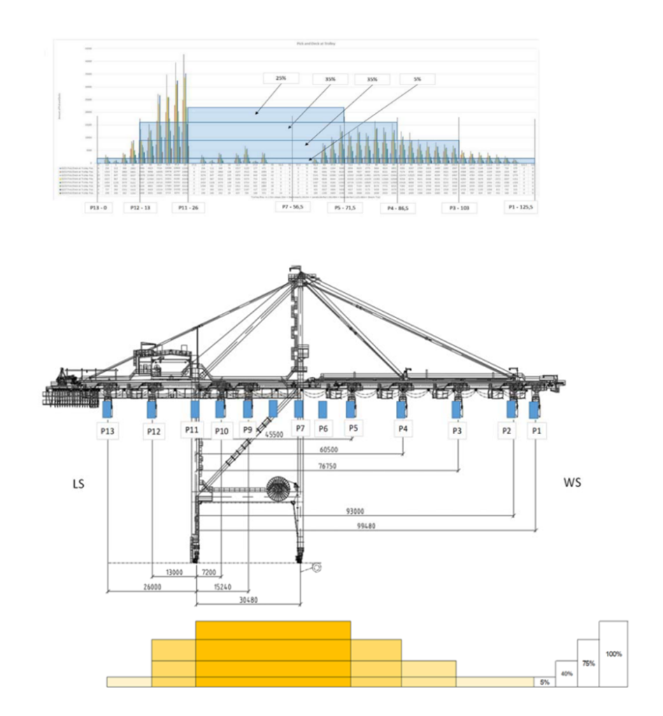
Engineers can build hundreds or even thousands of load combinations which will take into account any conditions that may occur to the crane structure. Load combinations can be combined into the load groups, which are envelope set of results. With SDC Verifier, it is possible to create fatigue groups, which allows to combine cases in certain position and assign a proper amount of cycles for them.
Automatic Welds Detection
Since fatigue mostly occurs on welds, it is important to find all welds in the model. SDC Verifier has a special weld finder tool which automatically detects welds, weld types and weld intersections on shell (plates) models to determine allowable stress range (which is called notch class, weld class or FAT class in different standards). It is also reorienting stresses from the elements’ coordinate system into the weld direction.
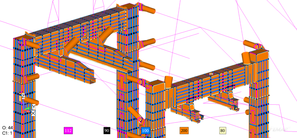
To automatically detect welds, Weld Finder takes into account every property change, every material change, thickness change or a connection of a certain angle to determine the elements that are forming this connection as weld. After that, SDC Verifier transforms the stresses into the weld directions. It allows to create weld classification since we know stresses along welds, perpendicular and in shear directions lead to the different fatigue strength depending on weld direction. For one million finite elements, it takes approximately a minute to find all welds.
Industry standards for Fatigue analysis in cranes structures
Fatigue analysis is not just a matter of predicting damage or finance. It is an industry standard. Companies have to comply with rules and regulations of specific standards if they want to get their crane certified. Within the library of SDC Verifier, it is possible to perform checks according to multiple rules and regulations of the certification societies or industry rules and regulation documents.
SDC Verifier implements specialized standards for cranes, like DIN 15018 (Cranes; steel structures; verification and analyses), EN 13001 (Crane safety – General design – Crane standard), F.E.M. 1.001 (Rules For The Design of Hoisting Appliances), and general, describing fatigue in steel structures – EN 1993-1-9 (Eurocode 3 Design of steel structures, Fatigue, 2005), FKM (5th and 6th editions) (Guideline Calculated strength verification of machine components), DVS 1612 (Steel Fatigue Check and Static Stress Check), DNV RP-C203 (Fatigue Design of Offshore Steel Structures April 2016). Every standard prescribes the quality of the welds to assign the S-N curve and to determine the fatigue strength for the welds.
When starting creating a check engineer need to indicate some parameters which SDC Verifier cannot retrieve from the model automatically, for example, choose the method of calculation like Limit State Design method (also known as Load And Resistance Factor Design (LRFD)) or Allowable Stress Design method (ASD), determine the specific resistance factor, etc. All formulas and calculation details in standards are open, and there is a possibility to create a custom check or modify an existing one. FEA results from the model can be used as variables in custom checks.
Results Accuracy
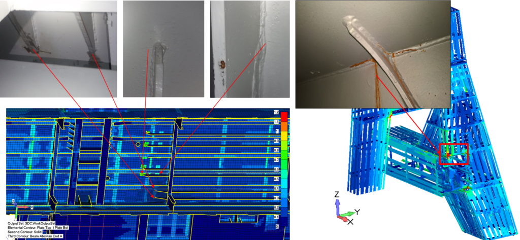
The results in SDC Verifier are determined within centimetres or millimetres in some cases, and it is possible to highlight some zones with a kind of crack. For example, one 30-cm crack was found under some double ceiling, so it was not spotted during the regular inspections, but after our evaluation and calculation report, a huge crack propagating in this area was found. It is possible not only precisely upgrade the design for the future if the problem has already happened, and also to simulate and understand why it happened and suggest improvements.
The functionality of the SDC Verifier not only allows to present results of fatigue checks for crane structures in various matters (plots, tables), but it also allows building a complete automatic template-based report of the calculation procedure, with model descriptions, general FEA results, code checks. When you have some last-minute fixes, design changes, improvements, or modifications, it is very easy to go back to the FEA software to apply changes (change the thicknesses, adjust the fillets, modify the weld type if necessary), recalculate everything and regenerate the same report once again.
It helps for the inspection plans and also for design improvement and comparison of different design stages. In cases of modification projects when compare stiffness and a fatigue damage before and after modifications, or any other results alike (stiffness, stress level, weld strength) just put two reports aside and compare the result before and after.
Competing with spreadsheets. Why SDC Verifier is better
An experienced engineer can perform residual lifetime and fatigue analysis manually in Excel or other spreadsheets, but in this case, one structural member under one loading condition is checked. SDC Verifier enables verification of a complete model under hundreds or thousands of loading combinations and does this on top of the general design in your FEA software. It saves time, ensuring results’ accuracy minimizing error risks.
It is possible to optimize the design based on weld parameters, cross-section of the beam element, the thickness of a plate.


