Updated September 11, 2026: Added steel roof verification, snow and wind load examples, and an updated optimisation workflow.
Steel frame verification requires more than checking whether calculated stresses remain below the material yield strength. Engineers also need to define the relevant design actions and load combinations, verify member resistance and stability, account for buckling behaviour, and check connections where required.
For roof structures, this becomes particularly important because snow and wind can govern different parts of the frame. Roof geometry, exposure, wind-pressure zones, member restraints, and effective lengths can all change which members control the design.
The Eurocode framework separates these tasks across different standards. Snow and wind actions are primarily covered by EN 1991, while the resistance and stability of steel members and connections are covered by EN 1993. In this article, we show how these parts come together in a practical steel-frame verification workflow using SDC Verifier.
A steel frame may contain hundreds or thousands of interconnected beams, columns, braces, joints, bolts, and welds. Each component transfers forces through the structure, while different loading scenarios can change which members become critical.
The challenge is therefore not simply calculating stresses. Engineers need to:
represent geometry, materials, restraints, and loads correctly;
generate the required load combinations;
identify structural members and their effective lengths;
verify cross-section resistance and member stability;
check relevant buckling modes and connections;
investigate members with excessive utilisation;
update the design and verify it again after changes.
This becomes especially important for roofs and other lightweight frames, where snow and wind actions can govern different load combinations and different parts of the structure.
SDC Verifier connects these stages to the underlying FEA model so that engineers can perform code checks using analysis results without transferring forces manually between separate calculation tools.
Step-by-Step Verification Process with SDC Verifier
Step 1: Model Setup and Load Application in Steel Frame Verification
Engineers first define the frame geometry, cross-sections, material properties, supports, and connections required to represent the structural behaviour.
Steel frame FEA model with beam members and detailed bolt and weld connection models.
Boundary conditions are particularly important because they influence load distribution, member forces, deflections, and stability behaviour.
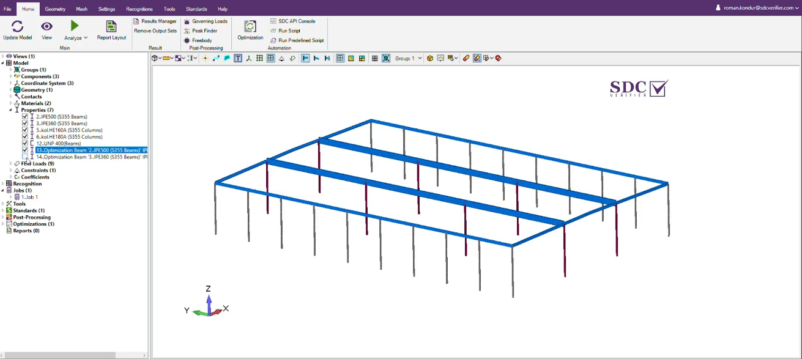
Boundary conditions applied to the steel frame model to represent the structural support conditions.
Loads can then be applied individually to represent the relevant design actions. Depending on the structure, these may include self-weight, permanent equipment loads, imposed loads, snow, wind, and other project-specific actions.
Example load cases applied to a steel frame model, including self-weight, equipment and platform loads, and wind in the X and Y directions.
For steel roofs, the loading model should reflect more than downward gravity loading. Snow may create significant vertical actions, while wind can produce both pressure and suction and may govern individual roof members under uplift conditions.
Model-scope note:beam-element models are well suited to evaluating global frame behaviour and member forces. They do not resolve local plate behaviour, detailed connection geometry, or local stress concentrations. Where these effects are important, additional shell or local models may be required.
Step 2: Load Combination Creation in Steel Frame Verification
The individual load cases need to be combined for the relevant design situations.
Eurocode design does not simply require applying every action at its maximum value simultaneously. Permanent and variable actions are combined using the applicable partial and combination factors, with the relevant National Annex considered where required.
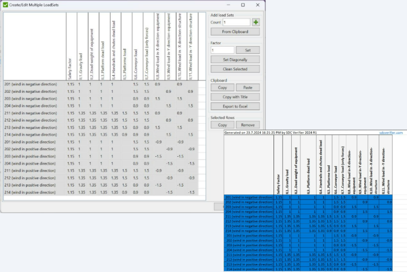
SDC Verifier allows engineers to define load combinations manually or generate combinations based on the selected design framework. Individual loads can be assigned to categories such as permanent, imposed, snow, or wind actions and then included in the required combinations.
Load combinations in SDC Verifier with safety and combination factors applied to individual load cases.
Load groups can then be created to organise these combinations into the sets required for analysis and verification, such as ultimate and serviceability limit-state envelopes.
Load groups in SDC Verifier used to organise load combinations into analysis and verification envelopes.
This provides a consistent set of analysis cases for the subsequent member and connection checks.
Steel Roof Verification Under Snow and Wind Loads
Steel roofs deserve specific attention because the governing design case may be very different from the gravity-dominated behaviour of other frame members.
Snow loads on steel roofs
Roof snow actions are addressed primarily in EN 1991-1-3 together with the applicable National Annex.
The design roof snow load depends on more than the characteristic snow load at ground level. Roof shape, exposure, thermal conditions, and the applicable shape coefficients affect how the action is transferred to the structure.
For example, a low-pitched roof may use a different snow distribution from a pitched, multi-span, cylindrical, or roof-adjacent configuration.
Examples of Eurocode roof snow-load shape coefficients for different roof geometries, including monopitch, pitched, multi-span, cylindrical, and roof-abutting configurations.
In practice, the roof snow action must be converted into loads applied to the relevant structural members. The selected coefficients and National Annex values determine the final roof snow pressure used in the model.
Example of roof snow-load calculation and application to the structural model based on ground snow load and the selected Eurocode coefficients.
Depending on the geometry, balanced and unbalanced snow arrangements may also need to be considered.
For the structural model, the important point is to convert these actions into realistic loads on the relevant roof members rather than treating snow as a generic global gravity value.
Wind pressure requires roof and wall zoning
Wind actions are primarily addressed by EN 1991-1-4 and the applicable National Annex.
One uniform wind pressure across an entire building is often insufficient for roof verification. External pressure coefficients vary with building geometry, wind direction, surface location, and the relevant wind zone.
Roof surfaces can therefore be divided into separate pressure zones. Edge and corner zones may experience different pressure or suction from central parts of the roof, meaning that different rafters, purlins, or supporting members can govern under different wind scenarios.
Roof wind zones used to apply different external pressure coefficients across the roof surface, including edge, corner, and central zones.
The same principle applies to walls. Windward, leeward, and side surfaces do not necessarily experience the same pressure, and wall zones near edges can differ from the rest of the façade.
Wall wind zones used to distribute wind pressure across windward, leeward, and side surfaces instead of applying one uniform wall load.
For this reason, a useful wind model should account for the required zones and wind directions rather than applying a single pressure indiscriminately across the complete frame.
Geometry, exposure, and restraints affect the result
The governing roof behaviour depends not only on load magnitude but also on how the frame transfers those loads.
Roof pitch, building dimensions, parapets, exposure conditions, member spacing, support conditions, bracing, and connectivity can all influence the forces reaching individual members.
The structural model and the assumptions used for the Eurocode checks therefore need to be consistent.
Effective length must be considered for both member axes
Member stability is another reason that a stress contour alone is insufficient.
A roof beam may be restrained differently about its major and minor axes. For example, intermediate restraints can reduce the effective length in one direction while the member remains effectively unrestrained over a longer distance in the other.
The effective lengths used for buckling verification should therefore reflect the actual restraint conditions for the relevant axes rather than assuming one physical member length applies to every instability mode.
SDC Verifier’s Beam Member Finder can recognise structural members and their strong- and weak-axis segmentation. Engineers can then review and adjust these definitions where the calculated member length does not represent the intended structural restraint.
Why a stress plot is not enough
An equivalent-stress plot is useful for reviewing the global FEA result and identifying highly stressed regions.
Equivalent stress distribution in the steel frame. Stress contours help identify highly stressed regions but do not by themselves verify member stability or Eurocode compliance.
However, a stress value below the steel yield strength doesnotby itself demonstrate that a member satisfies Eurocode stability requirements.
A slender member may be governed by flexural buckling, lateral-torsional buckling, torsional behaviour, or interactions between axial force and bending before material yielding becomes the controlling limit state.
Local and global instability should also be distinguished. Local buckling can reduce the effective resistance of a cross-section and may interact with overall member behaviour, but local buckling does not simply “accumulate” into global buckling.
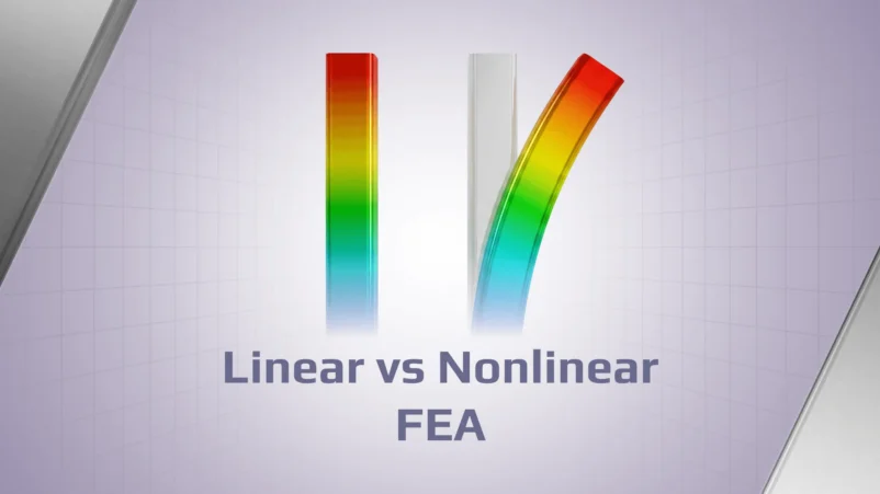
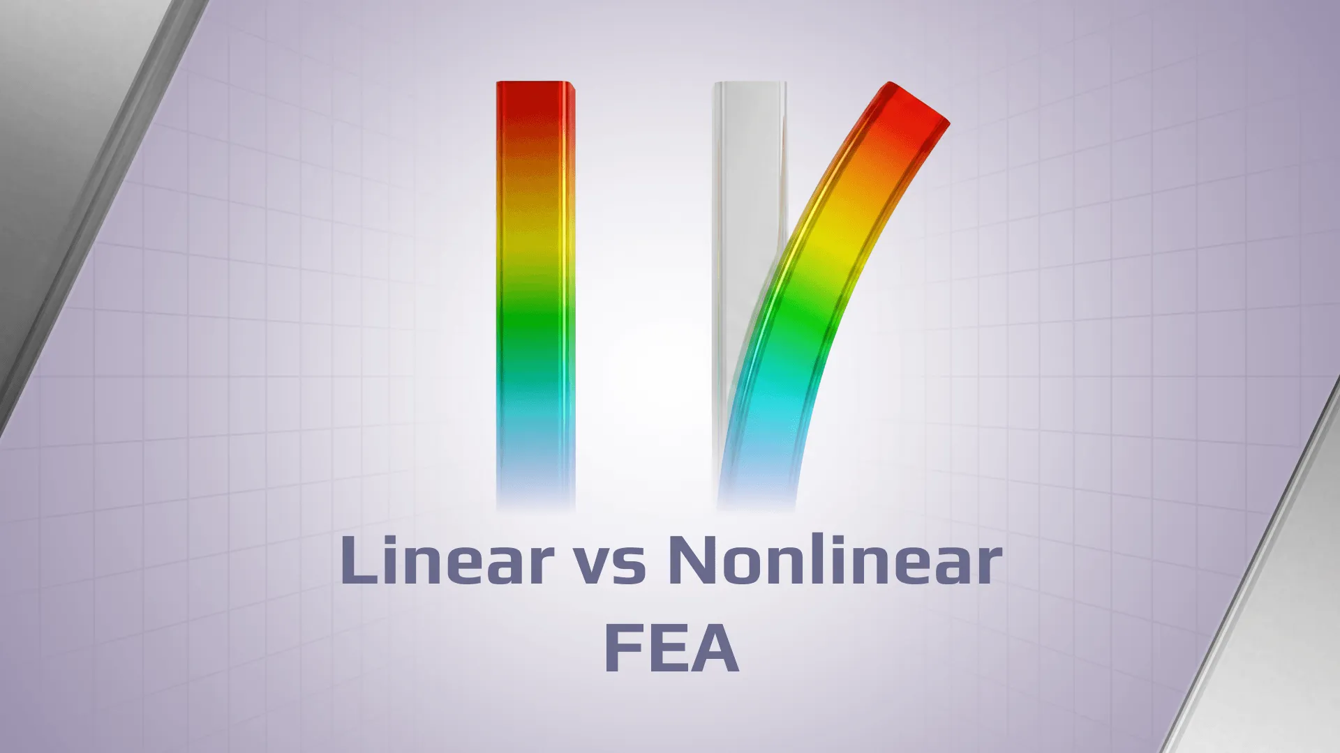
Similarly, linear eigenvalue buckling can identify idealised instability modes and load multipliers, but it does not replace code-based member checks or nonlinear analysis where imperfections, yielding, and second-order effects need to be represented.
The full video demonstrates the snow- and wind-load setup, roof zoning, member recognition, Eurocode 3 checks, optimisation, and recalculation workflow in SDC Verifier.
Step 3: Structural Member Recognition
Eurocode member verification operates on structural members rather than treating every finite element independently.
For beam models, this means the individual elements forming a physical beam, column, or brace need to be grouped into the correct structural members.
SDC Verifier’s Beam Member Finder automates much of this process. It identifies members based on model connectivity and provides the member information required for subsequent checks, including cross-section and orientation data.
A particularly important part of this workflow is reviewing member lengths and restraints about the relevant axes.
Beam Member Finder identifies structural member lengths separately in the Y and Z directions based on member connectivity and restraints.
A member can have a shorter restraint spacing about one axis and a longer unsupported length about the other. These definitions directly affect slenderness and buckling resistance, so they should be reviewed against the actual structural arrangement rather than accepted purely from geometry.
Beam Member Finder interface showing member segmentation, joint locations, and separate Y-, Z-, and torsional-length definitions.
Connection and weld recognition tools can similarly reduce the amount of manual geometry selection required before connection checks.
Step 4: Eurocode Compliance Checks
Once the structural analysis has been completed and members have been recognised, the resulting internal forces can be used for the relevant Eurocode checks.
For the steel-frame workflow discussed here, the main member resistance and stability checks are based on Eurocode 3.
Eurocode 3 Member Checks — EN 1993-1-1
EN 1993-1-1 provides rules for the resistance and stability of structural steel members.
In SDC Verifier, the Eurocode 3 member check can be added from the standards library and applied to the recognised structural members and relevant load combinations.
Eurocode 3 member, connection, weld, bolt, and buckling checks available in the SDC Verifier standards library.
Depending on the member and loading condition, the verification can include cross-section resistance and stability checks for axial force, shear, bending, flexural buckling, lateral-torsional buckling, and relevant interaction cases.
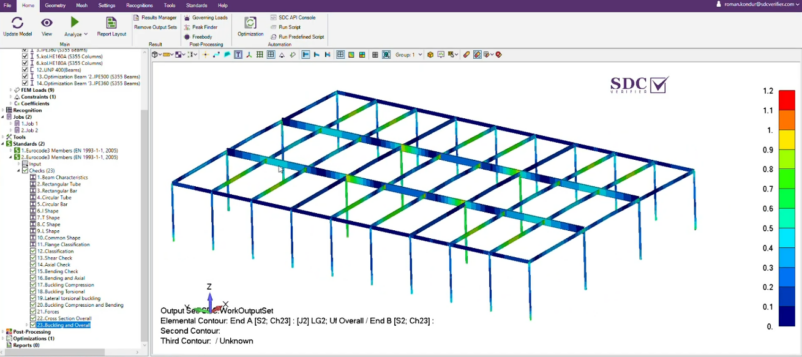
Eurocode 3 member-check utilisation across the steel frame, highlighting members approaching or exceeding the allowable utilisation limit.
Cross-section classification
Cross-section classification determines how the resistance of the section can be evaluated and how local plate slenderness affects its behaviour.
Eurocode 3 distinguishes Classes 1, 2, 3, and 4.
Classes 1–3 allow different levels of plastic or elastic resistance to be used. Class 4 sections require appropriate treatment of local plate buckling, such as effective-section rules where applicable.
The flange and web therefore need to be classified correctly before the corresponding resistance checks are interpreted.
Member slenderness and buckling
Buckling verification depends on more than the member’s physical end-to-end length.
Member slenderness and buckling resistance depend on the relevant axis, cross-section properties, restraint conditions, and the applicable Eurocode 3 buckling curves
Effective lengths in the major and minor directions should therefore represent the actual restraint system of the frame.
For beams susceptible to lateral-torsional buckling, the lateral and torsional restraint conditions also need to be represented appropriately.
Shear and combined resistance
Shear areas and resistance depend on the member cross-section.
Where high shear interacts with bending or other actions, the relevant Eurocode interaction or resistance reduction needs to be considered rather than evaluating each action independently.
The overall utilisation result then provides a practical way to identify the members and load combinations that govern the design.
Members with utilisation above 1.0 identified for further review and potential section optimisation.
Eurocode 3 Bolt Checks — EN 1993-1-8
Where bolted connections are part of the verification scope, EN 1993-1-8 provides the relevant design rules.
The verification can account for parameters including bolt geometry and position, threaded or unthreaded shear planes, edge distances, preload, friction class, bearing resistance, shear, tension, and their applicable interactions.
Example Eurocode 3 bolt-check criteria plot for a bolted connection in the structural model.
For slip-resistant connections, the slip check should be interpreted separately from ultimate connection resistance. Exceeding a slip criterion represents a risk of relative movement under the corresponding design condition; it does not automatically mean that the entire connection has reached structural failure.
Bolt-check results showing utilisation for the relevant resistance and slip criteria across individual fasteners.
Eurocode 3 Weld Checks — EN 1993-1-8
Welded connections also need to be evaluated using the applicable EN 1993-1-8 requirements.
SDC Verifier can use recognised weld geometry and calculated forces or weld stresses to perform the configured weld checks and report utilisation for the relevant weld segments.
This makes it possible to include member, bolt, and weld verification within the same model-based workflow where these checks are part of the project scope.
Eurocode 3 weld-check results with governing load case, weld geometry, calculation details, and overall utilisation.
Step 5: Optimise Failing Members — Then Reanalyse the Structure
When a member exceeds the allowable utilisation, increasing or otherwise changing its cross-section may be an appropriate design response.
SDC Verifier’s beam section optimisation workflow can evaluate candidate cross-sections against a selected code-check criterion and shortlist sections that reduce utilisation to the required range.
Optimisation results showing candidate cross-sections and their preliminary utilisation based on the existing analysis results.
There is, however, an important limitation to understand.
The first optimisation pass uses the internal forces from the existing structural analysis. When candidate section properties are evaluated against those unchanged forces, the result is anapproximation and a screening step, not the final verification of the modified structure.
Changing a beam or column section changes its stiffness. That can redistribute forces through the frame, alter deflections, and change which members or load combinations govern the design.
The correct workflow is therefore:
Identify members that do not satisfy the selected Eurocode check.
Use optimisation to shortlist suitable candidate cross-sections.
Apply the selected sections to the structural model.
Rerun the structural analysis with the updated stiffness properties.
Rerun the Eurocode member checks using the new analysis results.
Confirm that the updated frame satisfies the required utilisation limits and that the modification has not created new critical members elsewhere.
A candidate section should only be accepted after this updated analysis and verification cycle.
This distinction is particularly important when several roof members are being resized because stiffness redistribution can affect neighbouring members and the overall load path.
Step 6: Generate and Update the Verification Report
The final verification needs to remain traceable.
SDC Verifier’s Report Designer can bring together model information, load definitions, load combinations, calculation settings, member-check results, utilisation tables, and plots directly from the project.
Results can therefore remain linked to the underlying calculation instead of being manually copied into a separate report.
This is also useful during design iterations. If member sizes or other model parameters change, engineers can rerun the analysis and verification and update the report using the revised results.
For a steel roof or frame, the completed workflow therefore connects:
model setup → Eurocode actions → load combinations → structural analysis → member recognition → Eurocode member and connection checks → optimisation → reanalysis → final verification → reporting.
The important point is that none of these stages should be treated in isolation. A low stress plot does not prove member stability, an optimisation result based on existing forces is not a final design, and a section change should not be accepted until the updated structure has been analysed and checked again.
SDC Verifier brings these stages into one workflow so engineers can move from FEA results to Eurocode verification, design iteration, and reporting without rebuilding the calculation process manually.
Verify Steel Frames to Eurocode Directly from Your FEA Model
Run Eurocode member, bolt, weld, and stability checks, identify critical members, optimise cross-sections, and update reports in one workflow with SDC Verifier.